|
|
|
| Calibration method of laser displacement sensor based on binocular vision |
Hao-ran MA( ),Ya-bin DING*() ),Ya-bin DING*() |
| School of Mechanical Engineering, Tianjin University, Tianjin 300350, China |
|
|
|
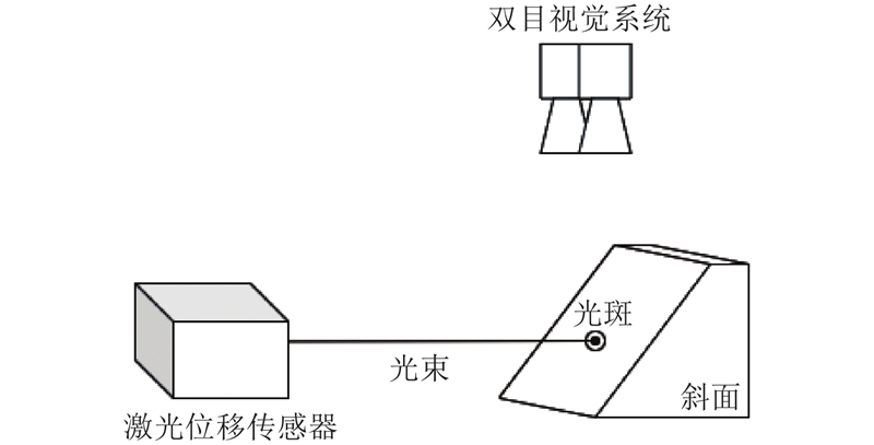
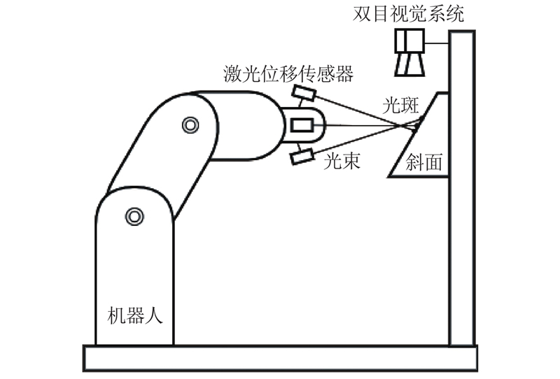
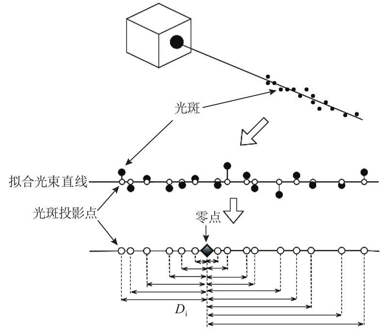
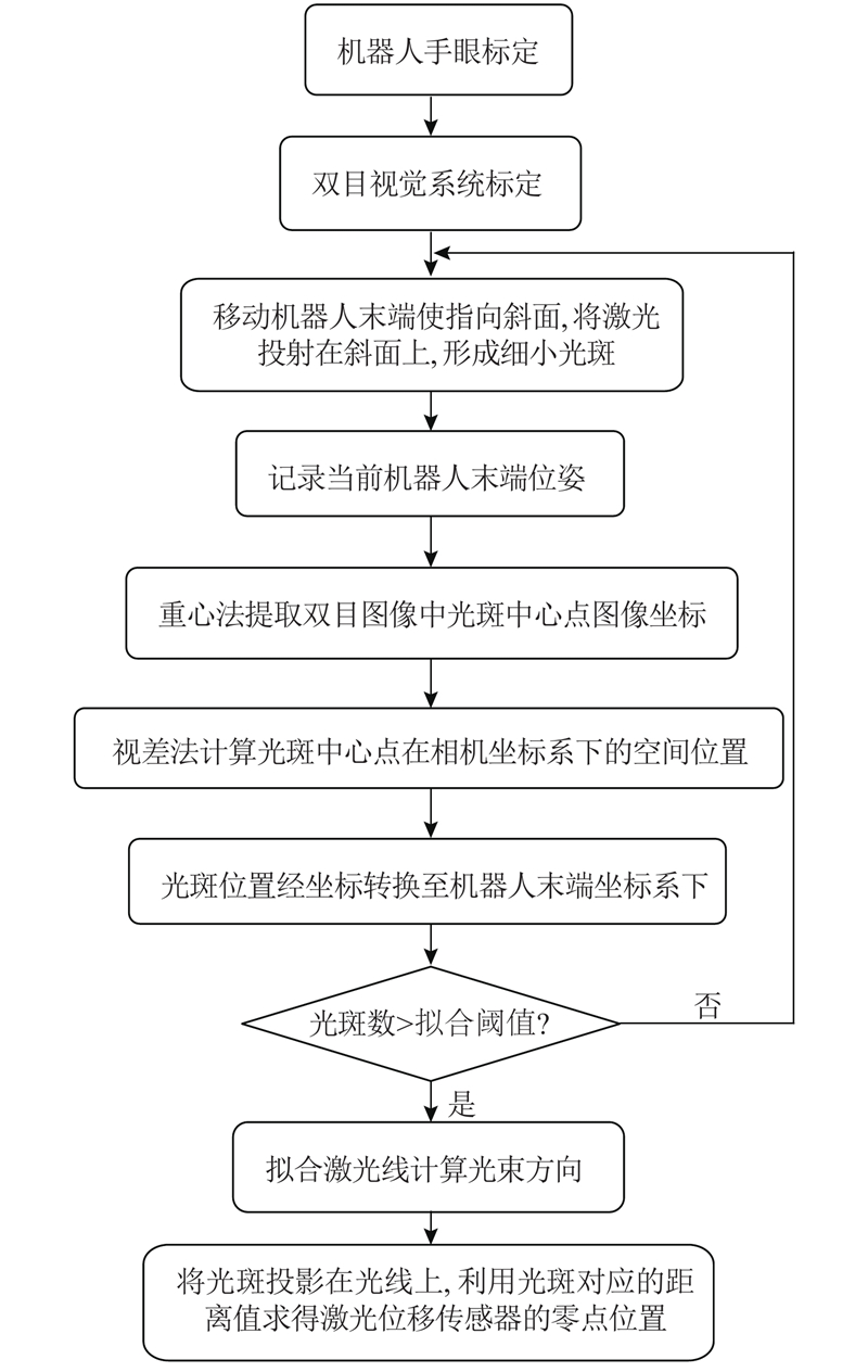
Abstract A laser displacement sensor calibration method based on binocular visual technology was proposed, in order to increase the calibration precision of laser displacement sensor under the robot end-effector coordinate system. Through binocular visual technology, the location of laser spots projected on the flat was reconstructed. The eye-to-hand calibration parameters were used to transform the light spots into the robot end-effector coordinate system, meanwhile least squares method were used to match light spots into the line of the laser beam and obtain the beam direction as well as zero position of the laser displacement sensor to complete calibration. This method can simultaneously calibrate multiple laser displacement sensors on the robot end-effector coordinate system. No auxiliary component with precision requirement is needed in the calibration process, so the precision is high and the robustness is strong. Result based on standard ball measurement precision evaluation experiment shows that the laser displacement sensor measurement precision range after calibration by this method is 0.038 6±0.025 8 mm, within the range of three standard deviation, which satisfies the requirement of robot processing.
|
|
Received: 22 September 2020
Published: 20 October 2021
|
|
|
| Fund: 国家重点研发计划资助项目(2017YFB1301800);国家自然科学基金资助项目(51775376,91948301,51721003,51675369);天津市自然科学基金资助项目(17JCZDJC40100) |
|
Corresponding Authors:
Ya-bin DING
E-mail: mahaoran@tju.edu.cn;ybding@tju.edu.cn
|
基于双目视觉的激光位移传感器标定方法
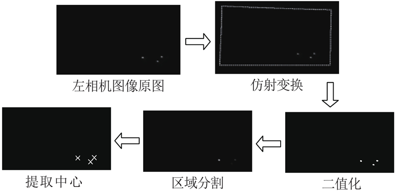
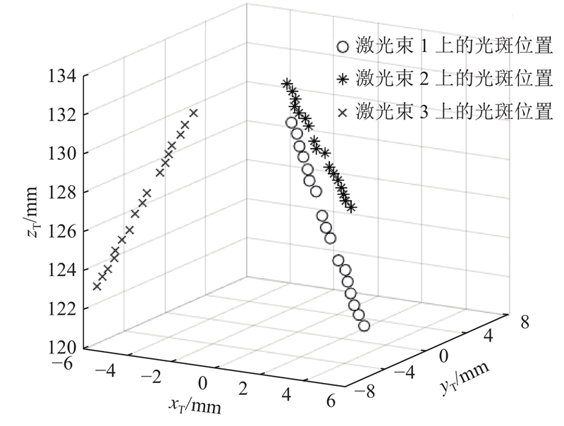
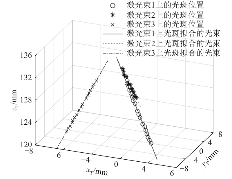
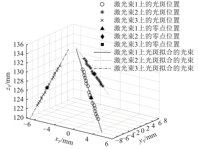
为了提高激光位移传感器在工业机器人末端坐标系下的标定精度,提出基于双目视觉的激光位移传感器标定方法. 该方法通过双目视觉技术重建激光光束投影在平面上的光斑位置,利用手眼标定参数将光斑位置转换至机器人末端坐标系,同时利用最小二乘方法将光斑拟合成光束直线,获得机器人末端坐标系下的传感器光束方向及零点位置以完成标定. 该方法可同时标定机器人末端上的多个激光位移传感器,无须采用有精度要求的辅助工件标定,具备精度高,鲁棒性强优势. 基于标准球的精度评价实验结果显示,在3倍标准差范围内该方法标定后的激光位移传感器测量精度范围为0.038 6±0.025 8 mm,满足机器人加工要求.
关键词:
双目视觉系统,
激光位移传感器,
测量系统,
传感器标定,
工业机器人
|
|
| [1] |
ZHANG J, SUN J, LIU Z A flexible calibration method for laser displacement sensors based on a stereo-target[J]. Measurement science and Technology, 2014, 25 (10): 105103
doi: 10.1088/0957-0233/25/10/105103
|
|
|
| [2] |
孙彬, 李兵 一种量化的激光位移传感器倾角误差补偿模型[J]. 仪器仪表学报, 2015, 36 (5): 996- 1004
SUN Bin, LI Bing A quantitative error compensation model of the inclination angle of the laser displacement sensor[J]. Chinese Journal of Scientific Instrument, 2015, 36 (5): 996- 1004
doi: 10.3969/j.issn.0254-3087.2015.05.005
|
|
|
| [3] |
宁光芳, 甘泉 激光位移传感器误差补偿的仿真分析[J]. 激光杂志, 2016, 37 (4): 37- 40
NING Guang-fang, GAN Quan Simulation and analysis of error compensation of laser displacement sensor[J]. Laser Journal, 2016, 37 (4): 37- 40
|
|
|
| [4] |
董祉序, 孙兴伟, 刘伟军, 等 基于激光位移传感器的自由曲面精密测量方法[J]. 仪器仪表学报, 2018, 39 (12): 30- 38
DONG Zhi-xu, SUN Xing-wei, LIU Wei-jun, et al Precision measurement method of free-form curved surfaces based on laser displacement sensor[J]. Chinese Journal of Scientific Instrument, 2018, 39 (12): 30- 38
|
|
|
| [5] |
BROSED J F, AGUILAR J J, GUILLOMIA D, et al 3D geometrical inspection of complex geometry parts using a novel laser triangulation sensor and a robot[J]. Sensors, 2011, 11 (1): 90- 110
|
|
|
| [6] |
YANG T, WANG Z, WU Z, et al. Calibration of laser beam direction for inner diameter measuring device [J]. Sensors, 2017, 17(2): 294.
|
|
|
| [7] |
GAO Y H, WU D, NAN C G, et al Normal direction measurement in robotic drilling and precision calculation[J]. International Journal of Advanced Manufacturing Technology, 2015, 76: 1311- 1318
doi: 10.1007/s00170-014-6320-7
|
|
|
| [8] |
WANG Z, BAI J, ZHANG X Y, et al Base detection research of drilling robot system by using visual inspection[J]. Journal of Robotics, 2018, 2018: 8767531
|
|
|
| [9] |
LONG Y, ZHANG Y L, BI Q Z, et al Research on surface normal measurement and adjustment in aircraft assembly[J]. Precision Engineering, 2017, 50: 482- 493
doi: 10.1016/j.precisioneng.2017.07.004
|
|
|
| [10] |
刘勇, 毕超, 刘京亮, 等 光学测头光束方向多种标定方法的研究与比较[J]. 测控技术, 2014, 33: 552- 554
LIU Yong, BI Chao, LIU Jing-liang, et al Study and compare of several methods of beam-direction of optical sensor[J]. Measurement and Control Technology, 2014, 33: 552- 554
|
|
|
| [11] |
曹双倩, 袁培江, 陈冬冬, 等 激光测距传感器光束矢向和零点位置标定方法[J]. 北京航空航天大学学报, 2018, 44 (6): 1321- 1327
CAO Shuang-qian, YUAN Pei-jiang, CHEN Dong-dong, et al Calibration method for laser beam direction and zero point of laser displacement sensor[J]. Journal of Beijing University of Aeronautics and Astronautics, 2018, 44 (6): 1321- 1327
|
|
|
| [12] |
毕超, 房建国, 刘京亮, 等 基于球形目标的激光位移传感器光束方向标定[J]. 光学精密工程, 2015, 23 (3): 678- 685
BI Chao, FANG Jian-guo, LIU Jing-liang, et al Calibration of beam direction of laser displacement sensor based on spherical target[J]. Optics and Precision Engineering, 2015, 23 (3): 678- 685
doi: 10.3788/OPE.20152303.0678
|
|
|
| [13] |
ZHOU A, GUO J, SHAO W, et al A segmental calibration method for a miniature serial-link coordinate measuring machine using a compound calibration artefact[J]. Measurement Science and Technology, 2013, 24 (6): 065001
doi: 10.1088/0957-0233/24/6/065001
|
|
|
| [14] |
王胜华, 都东, 张文增, 等 机器人定点变位姿手−眼标定方法[J]. 清华大学学报: 自然科学版, 2007, 47 (2): 165- 168
WANG Sheng-hua, DU Dong, ZHANG Weng-zeng, et al Hand-eye calibration for the robot by measuring a fixed point from different poses[J]. Journal of Tsinghua University: Science and Technology, 2007, 47 (2): 165- 168
|
|
|
| [15] |
WANG Z, YANG T Y, WANG L, et al Calibration of laser beam direction based on monocular vision[J]. Journal of Measurement Science and Instrumentation, 2017, 8 (4): 354- 363
|
|
|
| [16] |
陈和, 杨志浩, 郭磐, 等 激光光斑中心高精度定位算法研究[J]. 北京理工大学学报, 2016, 36 (2): 181- 185
CHEN He, YANG Zhi-hao, GUO Pan, et al Research of the high precision laser spot center location algorithm[J]. Transaction of Beijing Institute of Technology, 2016, 36 (2): 181- 185
|
|
|
| [17] |
罗世民, 李茂西 双目视觉测量中三维坐标的求取方法研究[J]. 计算机工程与设计, 2006, 27 (19): 3622- 3624
LUO Shi-min, LI Mao-xi Research on how to get object's 3D coordinate on two CCD camera measure system[J]. Computer Engineering and Design, 2006, 27 (19): 3622- 3624
doi: 10.3969/j.issn.1000-7024.2006.19.037
|
|
|
| [18] |
CHANG W C Precise positioning of binocular eye-to-hand robotic manipulators[J]. Journal of Intelligent and Robot Systems, 2007, 49 (3): 219- 236
doi: 10.1007/s10846-007-9135-z
|
|
|
| [19] |
刘强, 杨道国, 郝卫东 UR10机器人的运动学分析与轨迹规划[J]. 机床与液压, 2019, 47 (17): 22- 28
LIU Qiang, YANG Dao-guo, HAO Wei-dong Kinematic analysis and trajectory planning of UR10 robot[J]. Machine Tool and Hydraulics, 2019, 47 (17): 22- 28
doi: 10.3969/j.issn.1001-3881.2019.17.005
|
|
|
| [20] |
GONG M, YUAN P, WANG T. A novel method of surface-normal measurement in robotic drilling for aircraft fuselage using three laser range sensors [C]// IEEE/ASME International Conference on Advanced Intelligent Mechatronics. Kaohsiung: IEEE, 2012: 450-455.
|
|
|
| [21] |
闫航瑞, 熊志勇 表面倾斜对激光三角测量的影响及校正研究[J]. 光学仪器, 2014, 36 (1): 11- 14
YAN Hang-rui, XIONG Zhi-yong Study of the impact and correction of surface tilt upon laser triangulation[J]. Optical Instruments, 2014, 36 (1): 11- 14
doi: 10.3969/j.issn.1005-5630.2014.01.003
|
|
|
|
Viewed |
|
|
|
Full text
|
|
|
|
|
Abstract
|
|
|
|
|
Cited |
|
|
|
|
| |
Shared |
|
|
|
|
| |
Discussed |
|
|
|
|