|
|
|
| Design of wing mechanism with variable camber based on cross-spring flexural pivots |
Jun-heng XU1,2( ),Xiao-jun YANG1,*(),Bing LI1 ),Xiao-jun YANG1,*(),Bing LI1 |
1. School of Mechanical Engineering and Automation, Harbin Institute of Technology Shenzhen Graduate School, Shenzhen 518000, China
2. Shanghai Institute of Aerospace System Engineering, Shanghai 201108, China |
|
|
|
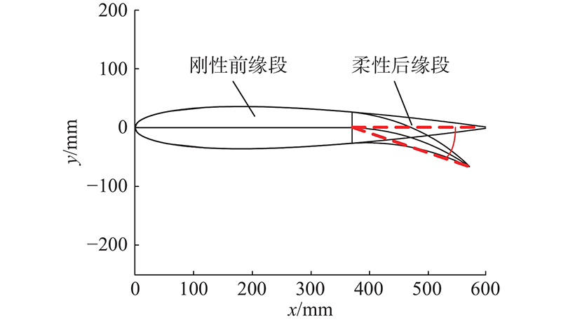
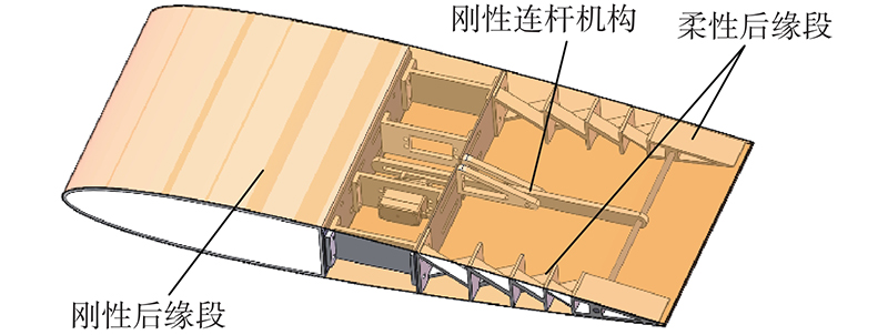
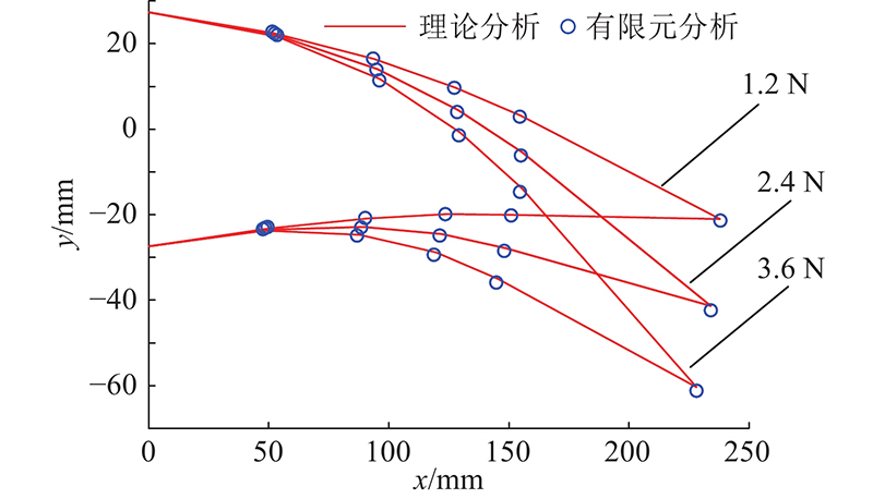
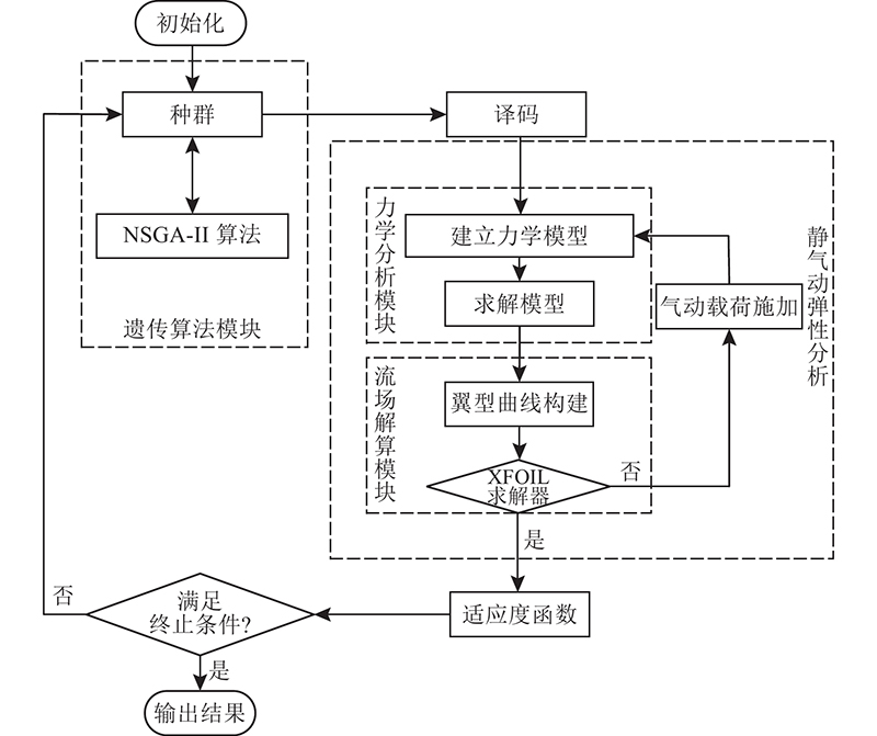
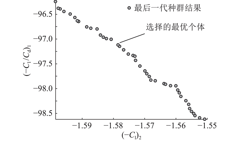
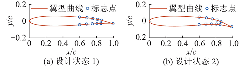
Abstract In order to design airfoil mechanism with continuous variable camber, a morphing wing structure and modeling analysis was proposed by using flexible trailing edge mechanism and rigid connecting rod driving mechanism. The wing mechanism was based on cross-spring flexural pivots. The theoretical mechanics model of the flexible trailing edge mechanism was established by using chained beam constraint model, and the relationship between the force and deformation of the mechanism was also obtained. Then, compared the theoretical mechanics model with finite element model. On the basis of the mechanical model, In order to improve the aerodynamic characteristics of the wing mechanism, NSGA-II multi-objective genetic algorithm was used to optimize the dimension parameters of the mechanism. After optimization, the lift-drag ratio of the morphing wing in cruise stage is increased by 1.09%, and the lift coefficient in takeoff stage is increased by 2.54%. The deformation precision and deformation range of the airfoil mechanism were tested by experiments.
|
|
Received: 21 April 2021
Published: 29 March 2022
|
|
|
| Fund: 深圳市国际合作研究资助项目(GJHZ20170313113529978) |
|
Corresponding Authors:
Xiao-jun YANG
E-mail: xujunheng0704@163.com;yangxiaojun@hit.edu.cn
|
基于交叉簧片式铰链的变弯度机翼机构设计
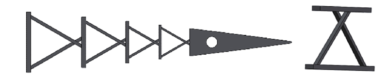
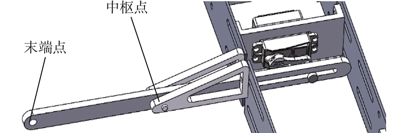
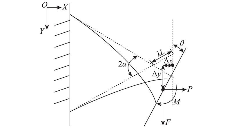
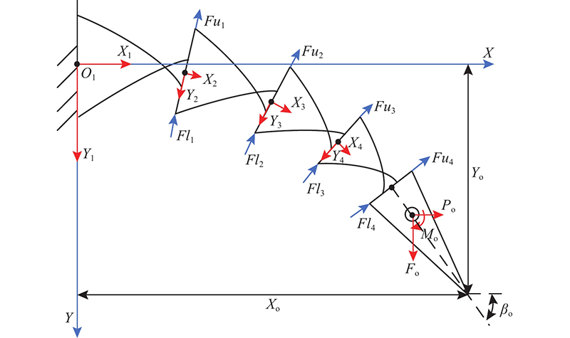
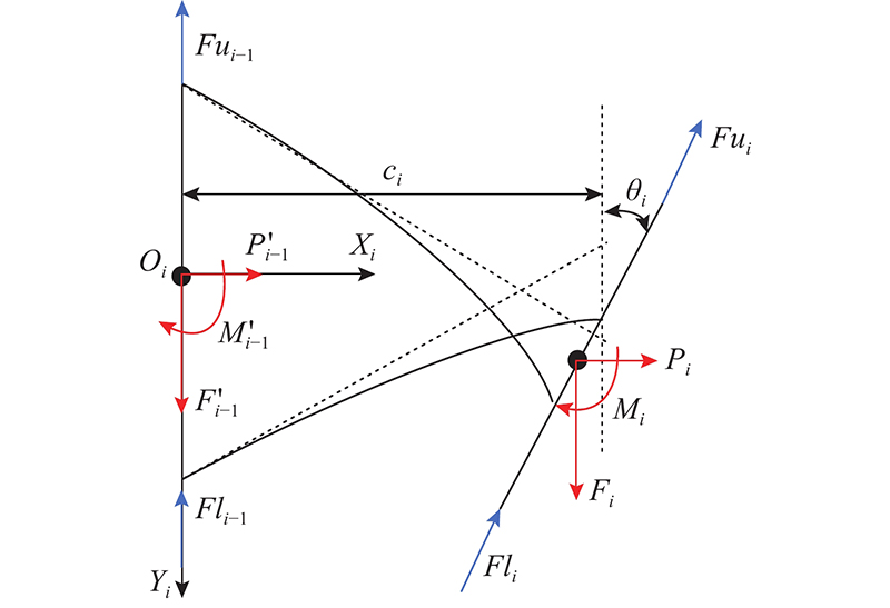
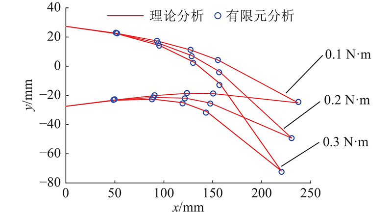
为了研究机翼弦向连续变弯度的设计问题,提出由柔性后缘机构与刚性连杆驱动机构组成的机翼变弯度设计方案以及建模分析方法. 基于交叉簧片式柔性铰链设计机翼机构构型. 采用链式梁约束建模方法,建立柔性后缘机构的理论力学模型,得到其受力和变形的关系,并利用有限元仿真对理论力学模型进行验证. 在力学模型的基础上,采用NSGA-II多目标遗传算法优化机翼机构的相关尺寸参数,提升机翼的气动特性. 经优化,机翼巡航阶段的升阻比提升1.09%,起降阶段的升力系数提高2.54%. 经实验验证了设计的变弯度机翼机构变弯度的精度和变弯度的范围.
关键词:
变弯度机翼,
柔性机构,
链式梁约束建模方法,
多目标优化,
气动性能
|
|
| [1] |
李小飞, 张梦杰, 王文娟, 等 变弯度机翼技术发展研究[J]. 航空科学技术, 2020, 31 (2): 12- 24
LI Xiao-fei, ZHANG Meng-jie, WANG Wen-juan, et al Research on variable camber wing technology development[J]. Aeronautical Science and Technology, 2020, 31 (2): 12- 24
|
|
|
| [2] |
GILBERT W W Mission adaptive wing system for tactical aircraft[J]. Journal of Aircraft, 1981, 18 (7): 597- 602
doi: 10.2514/3.57533
|
|
|
| [3] |
CAMPANILE L F Modal synthesis of flexible mechanisms for airfoil shape control[J]. Journal of Intelligent Material Systems and Structures, 2007, 19 (7): 779- 789
|
|
|
| [4] |
CAMPANILE L F, ANDERS S Aerodynamic and aeroelastic amplification in adaptive belt-rib airfoils[J]. Aerospace Science and Technology, 2005, 9 (1): 55- 63
doi: 10.1016/j.ast.2004.07.007
|
|
|
| [5] |
HASSE A, CAMPANILE L F Design of compliant mechanisms with selective compliance[J]. Smart Materials and Structures, 2009, 18 (11): 115016
doi: 10.1088/0964-1726/18/11/115016
|
|
|
| [6] |
DAYYANI I, KHODAPARAST H H, WOODS B K, et al The design of a coated composite corrugated skin for the camber morphing airfoil[J]. Journal of Intelligent Material Systems and Structures, 2015, 26 (13): 1592- 1608
doi: 10.1177/1045389X14544151
|
|
|
| [7] |
WOODS B K S, DAYYANI I, FRISWELL M I Fluid/structure-interaction analysis of the fish-bone-active-camber morphing concept[J]. Journal of Aircraft, 2015, 52 (1): 307- 319
doi: 10.2514/1.C032725
|
|
|
| [8] |
LI G, MIAO Z, LI B, et al Type synthesis to design variable camber mechanisms[J]. Advances in Mechanical Engineering, 2016, 8 (8): 2071835688
|
|
|
| [9] |
KUDER I K, ARRIETA A F, RAITHER W E, et al Variable stiffness material and structural concepts for morphing applications[J]. Progress in Aerospace Sciences, 2013, 63: 33- 55
doi: 10.1016/j.paerosci.2013.07.001
|
|
|
| [10] |
于靖军, 郝广波, 陈贵敏, 等 柔性机构及其应用研究进展[J]. 机械工程学报, 2015, 13 (51): 53- 68
YU Jing-jun, HAO Guang-bo, CHEN Gui-min, et al State-of-art of compliant mechanisms and their applications[J]. Journal of Mechanical Engineering, 2015, 13 (51): 53- 68
|
|
|
| [11] |
杨其资, 刘浪, 毕树生, 等 广义三交叉簧片柔性轴承的旋转刚度特性研究[J]. 机械工程学报, 2015, 51 (13): 189- 195
YANG Qi-zi, LIU Lang, BI Shu-sheng, et a1 Rotational stiffness characterization of generalized triple-cross-spring flexure pivots[J]. Journal of Mechanical Engineering, 2015, 51 (13): 189- 195
doi: 10.3901/JME.2015.13.189
|
|
|
| [12] |
ZHAO H, BI S Accuracy characteristics of the generalized cross-spring pivot[J]. Mechanism and Machine Theory, 2010, 45 (10): 1434- 1448
doi: 10.1016/j.mechmachtheory.2010.05.004
|
|
|
| [13] |
ZHAO H, BI S Stiffness and stress characteristics of the generalized cross-spring pivot[J]. Mechanism and Machine Theory, 2010, 45 (3): 378- 391
doi: 10.1016/j.mechmachtheory.2009.10.001
|
|
|
| [14] |
WITTRICK W H The properties of crossed flexure pivots, and the influence of the point at which the strips cross[J]. Aeronautical Quarterly, 1951, 2 (4): 272- 292
|
|
|
| [15] |
CHEN G, MA F, HAO G, et al Modeling large deflections of initially curved beams in compliant mechanisms using chained beam constraint model[J]. Journal of Mechanisms and Robotics, 2019, 11 (1): 011002
|
|
|
| [16] |
DEB K, PRATAP A, AGARWAL S, et al A fast and elitist multiobjective genetic algorithm: NSGA-II[J]. IEEE transactions on evolutionary computation, 2002, 6 (2): 182- 197
doi: 10.1109/4235.996017
|
|
|
|
Viewed |
|
|
|
Full text
|
|
|
|
|
Abstract
|
|
|
|
|
Cited |
|
|
|
|
| |
Shared |
|
|
|
|
| |
Discussed |
|
|
|
|