|
|
|
| Hardware efficient FFT design based on improved rotation factor |
Yang LUO( ),Wei ZHANG*() ),Wei ZHANG*() |
| School of Microelectronic, Tianjin University, Tianjin 300072, China |
|
|
|
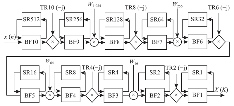
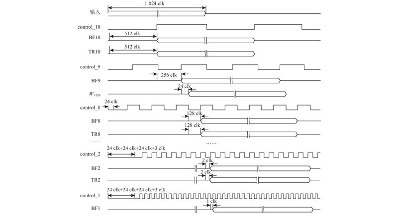
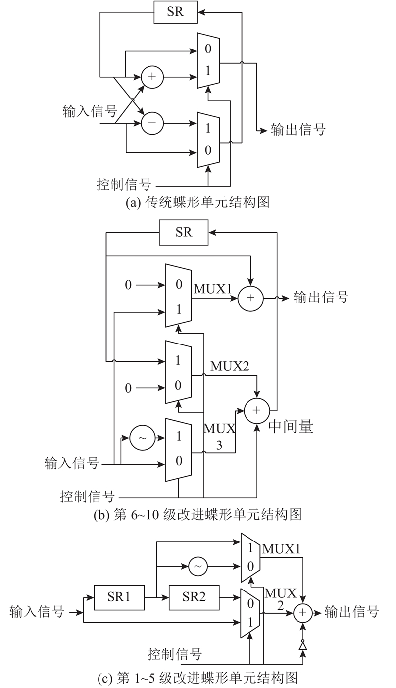
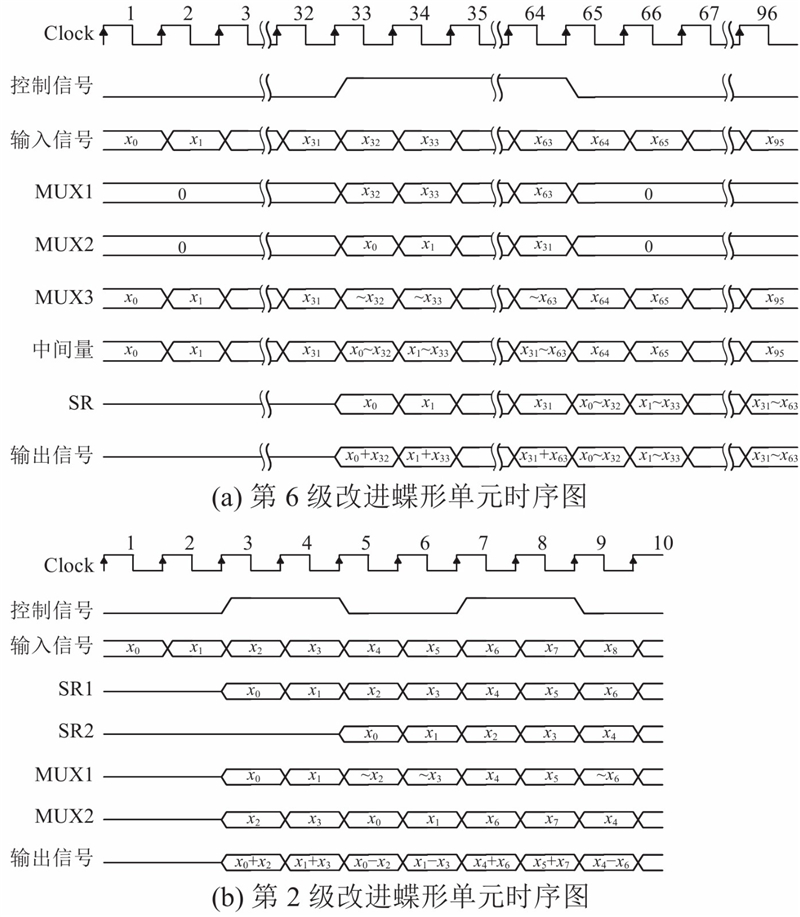
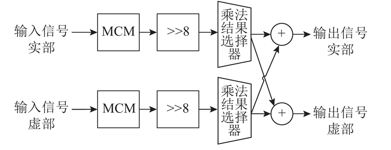
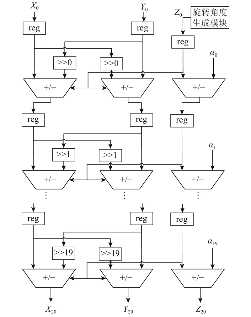
Abstract A hardware efficient Radix-22 fast Fourier transform based on a single-path delay feedback architecture was designed aiming at the problem that the rotation factor module takes up more resources in FFT hardware implementation. The method of mixing CORDIC and MCM was adopted to design the rotation factor module to realize FFT architecture without conventional multiplier and DSP48E resource. MCM method based on ternary adders was used to minimize the number of adders for the W16 rotation factor module with less rotation angles. CORDIC method was adopted for the rotation factor modules of W64, W256 and W1 024 with more rotation angles. The real-time generation module of rotation angles was designed according to the mathematical law of rotation angles. The method does not need to occupy ROM resources and avoids complex addressing logic and timing control compared with the traditional CORDIC method. The designed 16 bit 64-point FFT improves the throughput per slice by 35.20% on Xilinx Virtex-7, the 256-point FFT improves by 30.37% on Virtex-5, and the 1 024-point FFT improves by 25.38% on Virtex-7 compared with other architectures.
|
|
Received: 07 June 2020
Published: 30 July 2021
|
|
|
| Fund: 光电信息控制和安全技术重点实验室资助项目(JCKY2019210C053) |
|
Corresponding Authors:
Wei ZHANG
E-mail: 2018232032@tju.edu.cn;tjuzhangwei@tju.edu.cn
|
基于改进旋转因子的高性能FFT硬件设计
针对FFT硬件实现中旋转因子模块占用资源较多的问题,设计高性能单路延时反馈结构的基22快速傅里叶变换. 采用CORDIC与MCM混合的方法设计旋转因子模块,实现了无需常规乘法器的FFT架构,不必占用DSP48E资源. 对于旋转角度数量较少的W16旋转因子模块,采用基于三输入加法器的MCM方法设计,将加法器数量降到最低. 对于旋转角度数量较多的W64、W256和W1 024模块,采用CORDIC方法设计. 依据旋转角度的数学规律,设计旋转角度实时生成模块,与传统的CORDIC方法相比,不需要占用ROM资源,避免了复杂的寻址逻辑和时序控制. 与其他构架相比,设计的16 bit 64点快速傅里叶变换在Xilinx Virtex-7上将单位slice吞吐率提高了35.20%,256点FFT在Virtex-5上提高了30.37%,1 024点FFT在Virtex-7上提高了25.38%.
关键词:
快速傅里叶变换,
单路延迟反馈架构,
常数乘法器,
坐标旋转数字计算方法
|
|
| [1] |
GROGINSKY H L, WORKS G A A pipeline fast Fourier transform[J]. IEEE Transactions on Computers, 1970, 19 (11): 1015- 1019
|
|
|
| [2] |
HE S, TORKELSON M. A new approach to pipeline FFT processor[C]// International Parallel Processing Symposium. Hawaii: IEEE, 1996: 766-770.
|
|
|
| [3] |
GARRIDO M, QURESHI F, TAKALA J, et al. Hardware architectures for the fast Fourier transform[M]//SHUVRA S, LEUPERS R, TAKALA J, et al. Handbook of signal processing systems. Switzerland: Springer, 2018: 613-648.
|
|
|
| [4] |
QURESHI F. Optimization of rotations in FFTs[D]. Linköping: Linköping University, 2012.
|
|
|
| [5] |
GARRIDO M, HUANG S, CHEN S, et al The serial commutator FFT[J]. IEEE Transactions on Circuits and Systems II: Express Briefs, 2016, 63 (10): 974- 978
doi: 10.1109/TCSII.2016.2538119
|
|
|
| [6] |
INGEMARSSON C, KALLSTROM P, GUSTAFSSON O. Using DSP block pre-adders in pipeline SDF FFT implementations in contemporary FPGAs[C]// 22nd International Conference on Field Programmable Logic and Applications. Oslo: IEEE, 2012: 71-74.
|
|
|
| [7] |
INGEMARSSON C, GUSTAFSSON O SFF: the single-stream FPGA-optimized feedforward FFT hardware architecture[J]. Journal of Signal Processing Systems, 2018, 90 (11): 1583- 1592
doi: 10.1007/s11265-018-1370-y
|
|
|
| [8] |
MA Z G, YIN X B, YU F A novel memory-based FFT architecture for real-valued signals based on a radix-2 decimation-in-frequency algorithm[J]. IEEE Transactions on Circuits and Systems II: Express Briefs, 2015, 62 (9): 876- 880
doi: 10.1109/TCSII.2015.2435522
|
|
|
| [9] |
TANG A M, YU L, HAN F J, et al. CORDIC-based FFT real-time processing design and FPGA implementation[C]// 12th International Colloquium on Signal Processing and its Applications. Malacca: IEEE, 2016: 233-236.
|
|
|
| [10] |
SHI J Y, TIAN Y H, WANG M X, et al. A novel design of 1024-point pipelined FFT processor based on Cordic algorithm[C]// 2nd International Conference on Intelligent System Design and Engineering Application. Sanya: IEEE, 2012: 80-83.
|
|
|
| [11] |
MANKAR A, PRASAD N, DAS A D, et al Multiplier: less VLSI architectures for radix‐22 folded pipelined complex FFT core [J]. International Journal of Circuit Theory and Applications, 2015, 43 (11): 1743- 1758
doi: 10.1002/cta.2038
|
|
|
| [12] |
ZHANG J F, LIU H Z, CHEN T, et al Enhanced hardware efficient FFT processor based on adaptive recoding CORDIC[J]. Electronics and Electrical Engineering, 2013, 19 (4): 97- 103
|
|
|
| [13] |
MAHDAVI H, TIMARCHI S Area-time-power efficient FFT architectures based on binary-signed-digit CORDIC[J]. IEEE Transactions on Circuits and Systems I: Regular Papers, 2019, 66 (10): 3874- 3881
doi: 10.1109/TCSI.2019.2922988
|
|
|
| [14] |
MEYER-BASE U, MEYER-BASE A, HILBERG W. Coordinate rotation digital computer (CORDIC) synthesis for FPGA[C]// International Workshop on Field-programmable Logic. Berlin: Springer, 1994: 397–408.
|
|
|
| [15] |
VORONENKO Y, PUSCHEL M Multiplierless multiple constant multiplication[J]. ACM Transactions on Algorithms, 2007, 3 (2): 11- 49
doi: 10.1145/1240233.1240234
|
|
|
| [16] |
KUMM M, HARDIECK M, WILLKOMM J, et al. Multiple constant multiplication with ternary adders[C]// 23rd International Conference on Field Programmable Logic and Applications. Porto: IEEE, 2013: 1-8.
|
|
|
| [17] |
KUMM M. Multiple constant multiplication optimizations for programmable gate arrays [M]. Wiesbaden: Springer, 2016.
|
|
|
| [18] |
EHLIAR A. Optimizing Xilinx designs through primitive instantiation[C]// 7th FPGA World Conference. Copenhagen: ACM, 2010: 20-27.
|
|
|
| [19] |
MA Y K, LIANG H H. Implementation of a pipeline large-FFT processor based on the FPGA[C]// International Conference in Communications, Signal Processing and Systems. Harbin: Springer, 2017: 638-644.
|
|
|
| [20] |
NGUYEN H N, KHAN S A, KIM C H, et al A high-performance, resource-efficient, reconfigurable parallel-pipelined FFT processor for FPGA platforms[J]. Microprocessors and Microsystems, 2018, 60: 96- 106
doi: 10.1016/j.micpro.2018.04.003
|
|
|
| [21] |
VALENCIA D, ALIMOHAMMAD A Compact and high-throughput parameterizable architectures for memory-based FFT algorithms[J]. IET Circuits, Devices and Systems, 2019, 13 (5): 696- 703
doi: 10.1049/iet-cds.2018.5556
|
|
|
| [22] |
WANG Z, LIU X, HE B, et al A combined SDC-SDF architecture for normal I/O pipelined radix-2 FFT[J]. IEEE Transactions on Very Large Scale Integration Systems, 2015, 23 (5): 973- 977
doi: 10.1109/TVLSI.2014.2319335
|
|
|
| [23] |
NGUYEN H N, KHAN S A, KIM C H, et al A pipelined FFT processor using an optimal hybrid rotation scheme for complex multiplication: design, FPGA implementation and analysis[J]. Electronics, 2018, 7 (8): 137
doi: 10.3390/electronics7080137
|
|
|
|
Viewed |
|
|
|
Full text
|
|
|
|
|
Abstract
|
|
|
|
|
Cited |
|
|
|
|
| |
Shared |
|
|
|
|
| |
Discussed |
|
|
|
|