|
|
|
| Formation mechanism and geometric influence of tip clearance vortex structure around hydrofoil |
Hu ZHANG1,2( ),Feng-yuan ZUO2,De-sheng ZHANG1,Wei-dong SHI3,*() ),Feng-yuan ZUO2,De-sheng ZHANG1,Wei-dong SHI3,*() |
1. Research Center of Fluid Machinery Engineering and Technology, Jiangsu University, Zhenjiang 212013, China
2. School of Mechanical Technology, Wuxi Institute of Technology, Wuxi 214121, China
3. School of Mechanical Engineering, Nantong University, Nantong 226019, China |
|
|
|
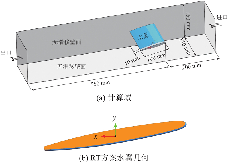
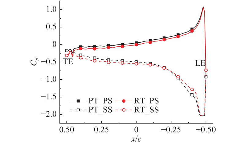
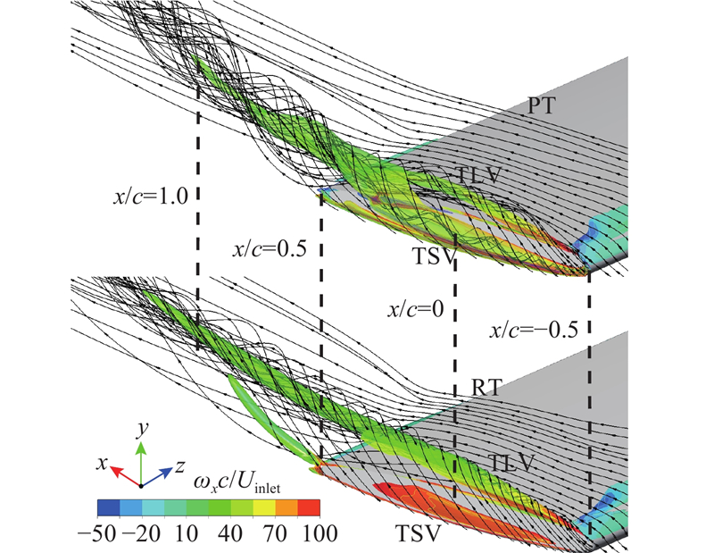
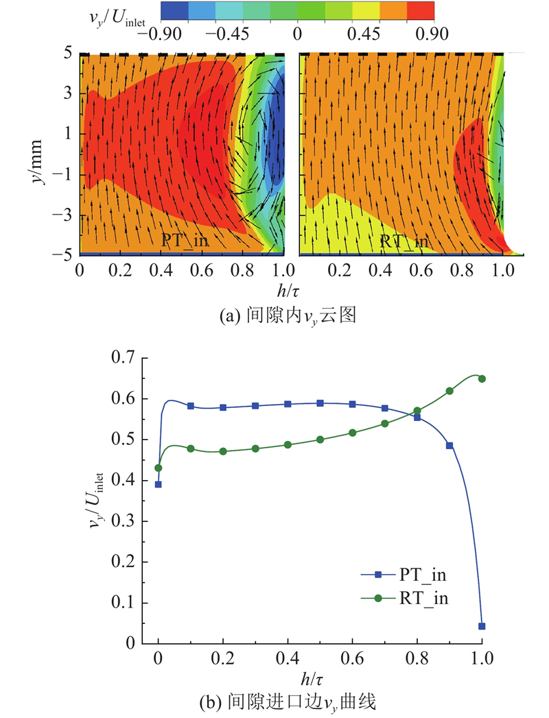
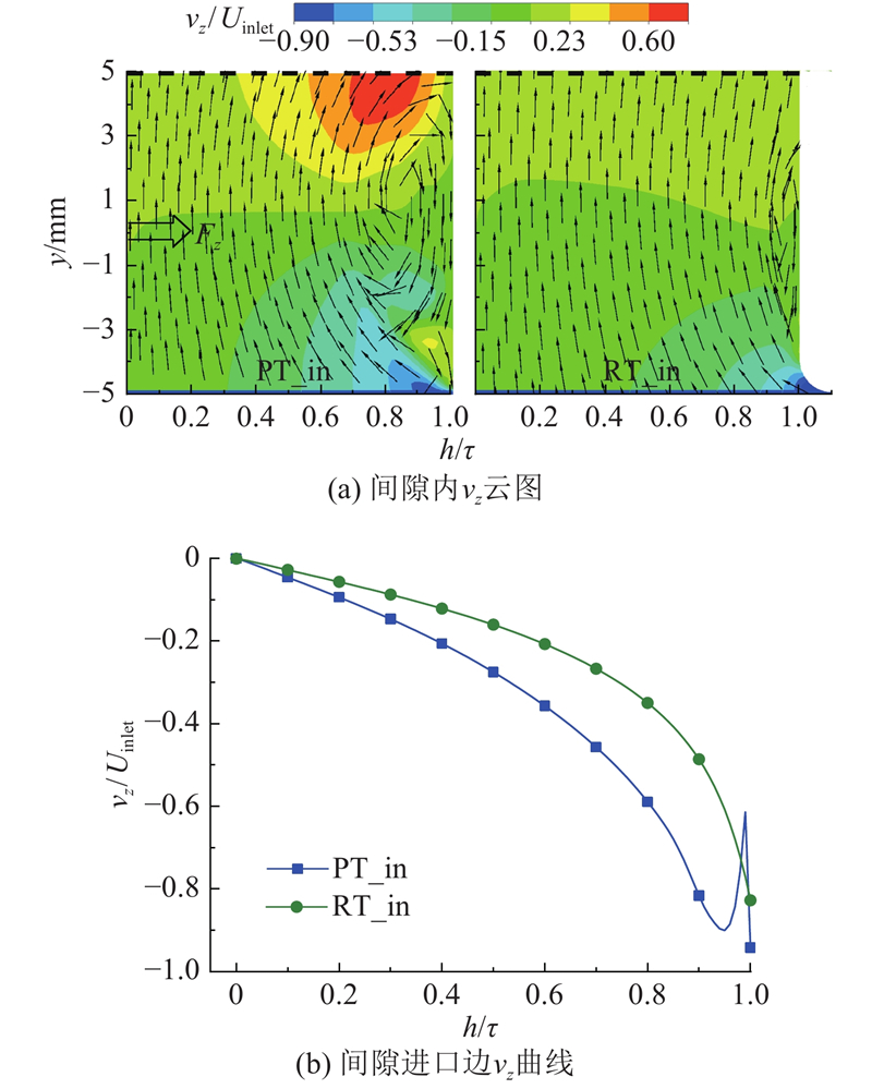
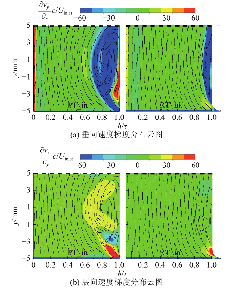
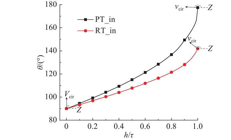
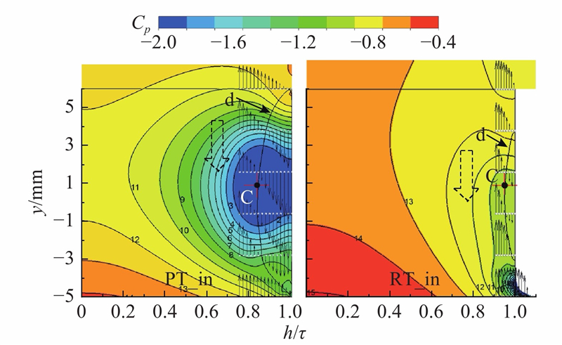
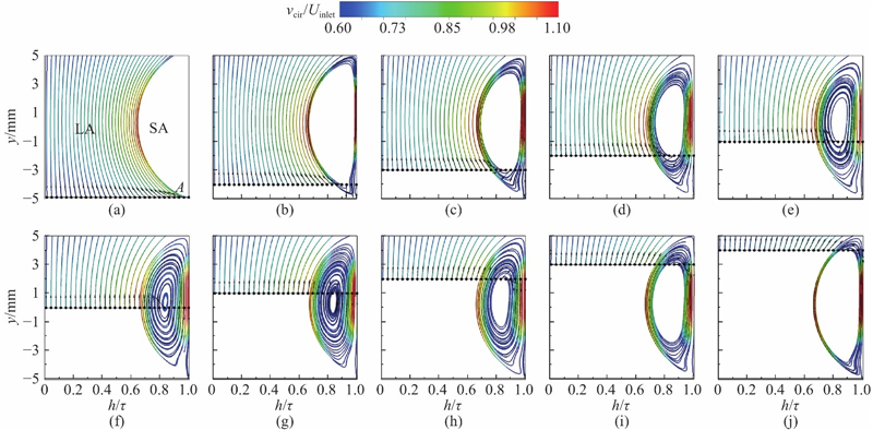
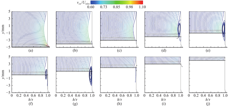
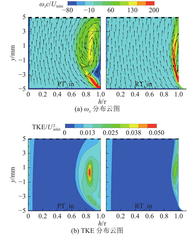
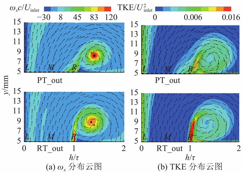
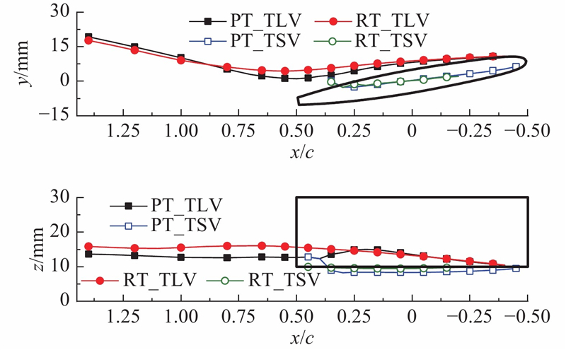
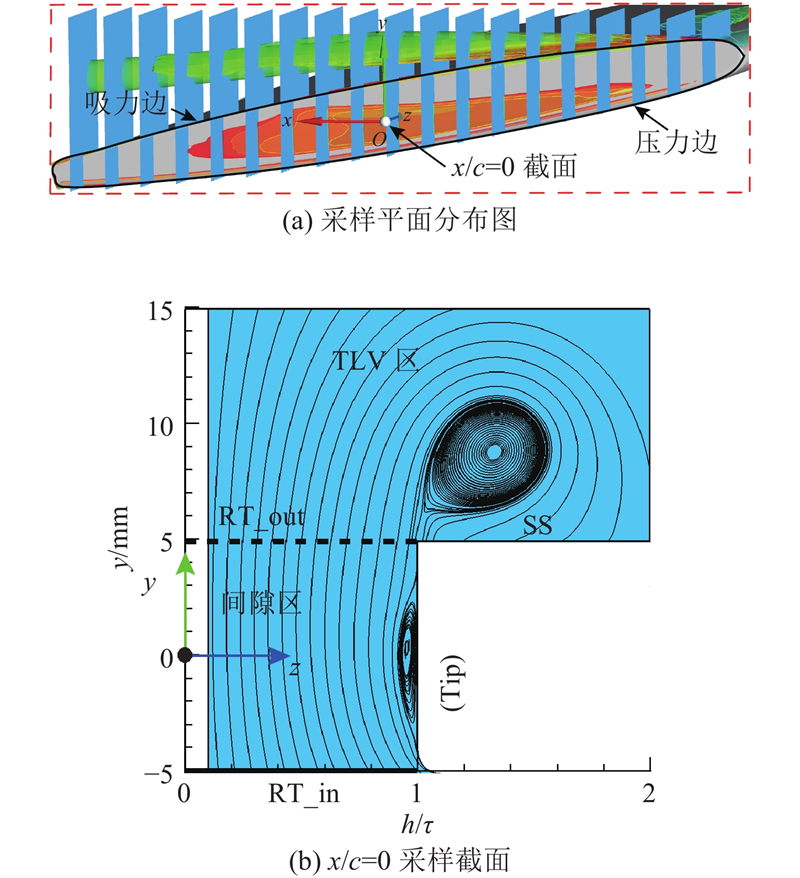
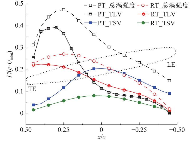
Abstract Numerical calculations of gap flow around the NACA0009 hydrofoil were conducted to analyze the formation mechanism of tip clearance vortex structure and the influence of the pressure edge fillet geometry. The three-dimensional visualization of gap flow characteristics and vortex structure was realized by applying streamline vorticity cloud diagram, and the vortex intensity was compared. The clearance inlet and outlet velocity and streamlines, pressure, turbulent kinetic energy in gap area were compared. Results showed that the fluid particles entering from the inlet side had a larger spanwise velocity of the plain tip geometry. The leakage flow gradually formed a crescent shaped separation zone in the tip clearance area, and transformed into tip separation vortex(TSV) under the adverse pressure gradient. The scale of TSV is positively related to the spanwise velocity. The formation of the tip leakage vortex (TLV) originated from the continuous shear action between the tip-leakage jet and the low-speed fluid on the suction side. The low-speed fluid, which obtained the energy transporting from the shear layer, eventually evolved into a stable tip leakage vortex structure. The clearance fillet geometry, which has an inhibitory effect on TSV, effectively reduces the gap vortex strength.
|
|
Received: 30 September 2019
Published: 31 December 2020
|
|
|
|
Corresponding Authors:
Wei-dong SHI
E-mail: zhanghutianxia@126.com;wdshi@ujs.edu.cn
|
绕水翼间隙涡结构形成机理与间隙几何影响
为了分析绕水翼间隙涡结构形成机理和探究压力边圆角几何的影响,对绕NACA0009水翼间隙流动进行数值计算. 通过流线涡量云图三维可视化分析,得到间隙流动特征及涡结构,对涡强度进行对比. 对翼形中截面间隙进出口边速度和间隙区平面流线、压力、湍动能进行比较分析. 研究发现:直角叶顶水翼泄漏流在间隙进口边有较大的展向速度,在间隙内形成新月形分离区,在逆压梯度作用下形成叶顶分离涡(TSV),涡尺度与展向速度成正相关;叶顶泄漏涡(TLV)形成源于间隙出口边射流与吸力边侧低速流体之间的持续剪切作用,低速流体从剪切层获得持续的能量输运形成稳定的泄漏涡结构;间隙压力边圆角对TSV起抑制作用,降低了间隙区整体涡强度.
关键词:
水翼,
圆角几何,
叶顶分离涡(TSV),
叶顶泄漏涡(TLV),
展向速度,
涡结构
|
|
| [1] |
TAN D, LI Y, WILKES L, et al Experimental investigation of the role of large scale cavitating vortical structures in performance breakdown of an axial waterjet pump[J]. Journal of Fluids Engineering, 2015, 137: 1- 14
|
|
|
| [2] |
ZHANG D, SHI L, SHI W, et al Numerical analysis of unsteady tip leakage vortex cavitation cloud and unstable suction-side-perpendicular cavitating vortices in an axial flow pump[J]. International Journal of Multiphase Flow, 2015, 77: 244- 259
doi: 10.1016/j.ijmultiphaseflow.2015.09.006
|
|
|
| [3] |
CHENG H, BAI X, LONG X, et al Large eddy simulation of the tip-leakage cavitating flow with an insight on how cavitation influences vorticity and turbulence[J]. Applied Mathematical Modelling, 2019, 77: 788- 809
|
|
|
| [4] |
SHI L, ZHANG D, ZHAO R, et al Effect of blade tip geometry on tip leakage vortex dynamics and cavitation pattern in axial-flow pump[J]. Sci China Tech Sci, 2017, 60 (10): 1480- 1493
doi: 10.1007/s11431-017-9046-9
|
|
|
| [5] |
GUO Q, ZHOU L, WANG Z Numerical evaluation of the clearance geometries effect on the flow field and performance of a hydrofoil[J]. Renewable Energy, 2016, 99: 390- 397
doi: 10.1016/j.renene.2016.06.064
|
|
|
| [6] |
王天壹, 宣益民 阶梯形凹槽对涡轮叶顶泄漏流的影响[J]. 中国科学, 2020, 50: 1- 10
WANG Tian-yi, XUAN Yi-ming Effect of stepped squealer tip on flow of leakage through turbine blade tip[J]. Sci Sin Tech, 2020, 50: 1- 10
doi: 10.1360/SST-2019-0204
|
|
|
| [7] |
LIU Y, TAN L Influence of C groove on suppressing vortex and cavitation for a NACA0009 hydrofoil with tip clearance in tidal energy[J]. Renewable Energy, 2020, 148: 907- 922
doi: 10.1016/j.renene.2019.10.175
|
|
|
| [8] |
DREYER M. Mind the gap: tip leakage vortex dynamics and cavitation in the axial turbines [D]. Lausanne: Swiss federal Institute of Technology in Lausanne(EPFL), 2015: 71-103.
|
|
|
| [9] |
DREYER M, DECAIX J, MUNCH-ALLIGNE C, et al Mind the gap: a new insight into the tip leakage vortex using stereo-PIV[J]. Experiments in Fluids, 2014, 55 (11): 1- 13
|
|
|
| [10] |
YOU D, WANG M, MOIN P, et al Effects of tip-gap size on the tip-leakage flow in a turbomachinery cascade[J]. Physics of Fluids, 2006, 18 (10): 105102
doi: 10.1063/1.2354544
|
|
|
| [11] |
YOU D, WANG M, MOIN P, et al Vortex dynamics and low-pressure fluctuations in the tip-clearance flow[J]. Journal of Fluids Engineering, 2007, 129 (8): 1002- 1014
doi: 10.1115/1.2746911
|
|
|
| [12] |
LABORDE R, CHANTREL P, MORY M, et al Tip clearance and tip vortex cavitation in an axial flow pump[J]. Journal of Fluids Engineering, 1997, 119 (3): 680- 685
doi: 10.1115/1.2819298
|
|
|
| [13] |
GIUNI M, GREEN R B Vortex formation on squared and rounded tip[J]. Aerospace Science and Technology, 2013, 29 (1): 191- 199
doi: 10.1016/j.ast.2013.03.004
|
|
|
| [14] |
DECAIX J, BALARAC G, DREYER M, et al RANS and LES computations of the tip-leakage vortex for different gap widths[J]. Journal of Turbulence, 2015, 16 (4): 309- 341
doi: 10.1080/14685248.2014.984068
|
|
|
| [15] |
SPALART P R, SHUR M On the sensitization of turbulence models to rotation and curvature[J]. Aerospace Science and Technology, 1997, 1 (5): 297- 302
doi: 10.1016/S1270-9638(97)90051-1
|
|
|
| [16] |
SMIRNOV P E, MENTER F R Sensitization of the SST turbulence model to rotation and curvature by applying the spalart–shur correction term[J]. Journal of Turbomachinery, 2009, 131 (4): 1- 8
|
|
|
| [17] |
GUO Q, ZHOU L, WANG Z, et al Numerical simulation for the tip leakage vortex cavitation[J]. Ocean Engineering, 2018, 151: 71- 81
doi: 10.1016/j.oceaneng.2017.12.057
|
|
|
|
Viewed |
|
|
|
Full text
|
|
|
|
|
Abstract
|
|
|
|
|
Cited |
|
|
|
|
| |
Shared |
|
|
|
|
| |
Discussed |
|
|
|
|