

SynRM转子结构的优化参数可以利用优化方法确定. Babetto等[10]采用差分算法对转子磁障径向肋宽进行优化,以提升SynRM转矩性能. Moghaddam等[11]采用响应面法与有限元相结合的方法,对SynRM的定转子进行优化设计,利用中心复合设计得到更精确的二次响应模型,以提升电机转矩、效率. Mirazimi等[12]通过保形映射计算转子磁障等效磁阻,采用等效磁路法建立磁路模型,以优化电机性能. 与有限元法相比,等效磁路法可以减少计算时间,但须利用有限元分析进行结果验证. 本文使用多目标蛇算法(multi-objective snake algorithm, MOSO)与有限元分析结合的方法,对SynRM转子结构进行优化设计,以提升电机转矩性能.
本文提出贝塞尔(Bezier)形转子结构,通过曲线拟合形成转子磁障形状. 为了降低转矩脉动,将非对称设计应用于SynRM转子结构设计中,引入磁障偏斜参数,使同一极下磁障关于
1. 非对称Bezier形转子结构
提出的Bezier形转子结构如图1所示. 利用经过磁障顶点和2个磁障末端点的等价二次Bezier曲线,确定磁障形状. 拟合点位置的改变影响转子磁障张角、磁障厚度与磁障偏移量,使磁障形状具有任意性.
图 1
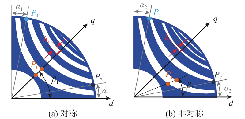
图 1 Bezier形转子结构的几何形状和参数
Fig.1 Geometry and parameter of Bezier-shaped rotor structure
改变相关结构参数,Bezier形转子可以形成类圆弧形和类双曲线形转子结构. 以圆弧形、双曲线形转子结构作为对比对象,如图2所示,验证Bezier形转子结构的优越性.
图 2
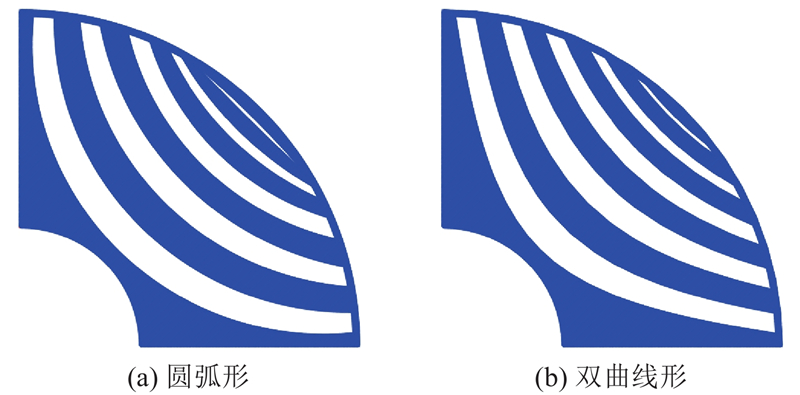
图 2 圆弧形和双曲线形转子结构的几何形状
Fig.2 Geometry of circular-shaped and hyperbolic-shaped rotor structure
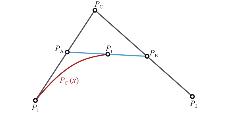
二次Bezier曲线利用起始点、终止点和控制点之间形成的两点线性插值,确定曲线形状. 该曲线经过起始点、终止点,通过调整控制点位置改变曲线形状. 二次Bezier曲线的形成原理如图3所示. 曲线
图 3
式中:
图 4
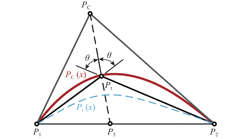
图 4 基于等价二次Bezier曲线的磁障边界形成原理
Fig.4 Formation principle of flux barrier boundary based on equivalent quadratic Bezier curve
定义
角平分线
式中:
以
联立式(6)、(7)可得
在推得角平分线
由此,形成等价二次Bezier曲线
表 1 电机的主要参数
Tab.1
| 参数 | 数值 |
| 定子外径 | 260 |
| 定子内径 | 170 |
| 定子槽数 | 36 |
| 转轴直径 | 60 |
| 气隙长度 | 0.5 |
| 铁心轴向长度 | 155 |
| 极对数 | 2 |
| 额定电流 | 12.7 |
图 5
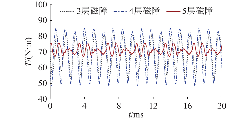
图 5 不同磁障层数下Bezier形转子结构的电机转矩曲线
Fig.5 Motor torque curve of Bezier-shaped rotor structure with different number of flux barrier layer
2. 非对称Bezier形转子结构的优化
2.1. 非对称Bezier形转子结构的优化参数及优化流程
非对称Bezier形转子结构的优化参数如图6所示. 图中,
图 6
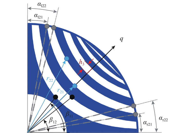
图 6 Bezier形转子结构的优化参数
Fig.6 Optimization parameter of Bezier-shaped rotor structure
图 7
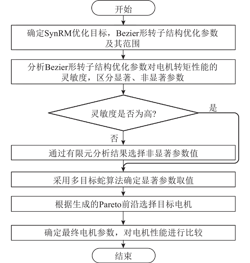
图 7 Bezier形转子结构的优化流程图
Fig.7 Optimization flow chart of Bezier-shaped rotor structure
2.2. 非对称Bezier形转子结构的优化设计
使用改进拉丁超立方采样生成实验设计点,通过斯皮尔曼秩法分析优化参数与优化目标之间的相关性. 基于方差分析的斯皮尔曼秩法的灵敏度分析模型可以表示为
式中:
图8给出5层磁障的Bezier形转子结构优化参数的灵敏度
图 8

图 8 25个转子结构优化参数对转矩性能的灵敏度
Fig.8 Sensitivity of 25 optimization parameters of rotor structure to torque performance
蛇算法(snake optimizer, SO)是由Hashim等[20]提出的新颖的元启发式优化算法. 该算法模拟蛇因食物、温度变化产生的觅食、战斗、繁殖等行为进行数学建模,是简单、高效的优化算法. 使用结合精英选择和轮盘赌法多目标优化策略的MOSO算法,对非对称Bezier形转子结构进行优化设计,优化目标及约束如下所示.
式中:
精英选择策略与轮盘赌法的作用机理如图9所示. 其中,精英选择策略将第
图 9
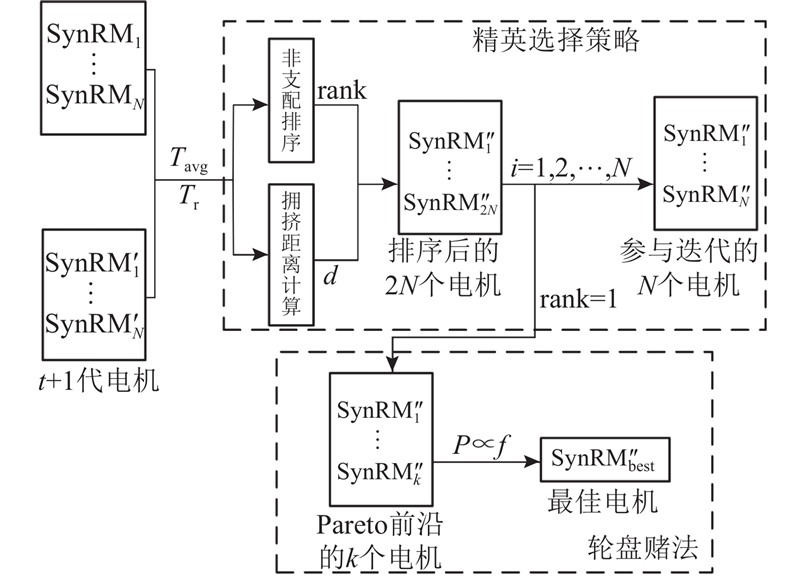
图 9 精英选择和轮盘赌在迭代中排序与参数寻优的机理
Fig.9 Mechanism of elite selection and roulette strategy for sorting and parameter optimization in iteration
图 10
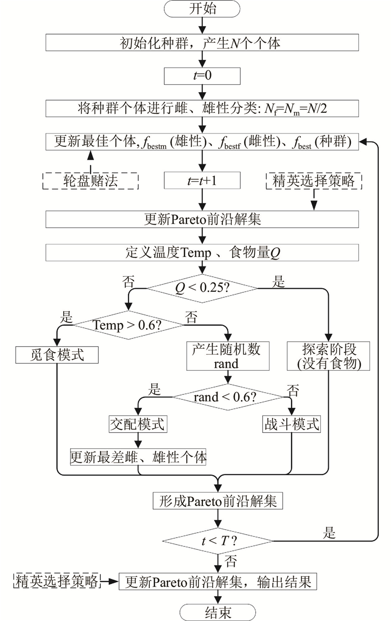
图 10 结合精英选择与轮盘赌的MOSO算法流程图
Fig.10 Flow chart of MOSO algorithm combining elite selection and roulette wheel selection method
图 11
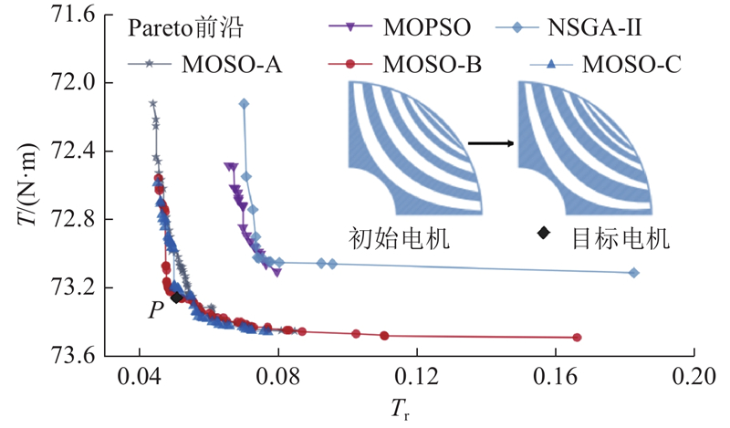
图 11 MOSO与其他算法对转矩性能的Pareto前沿解
Fig.11 Pareto frontier solution of MOSO and other algorithm for torque performance
相对多目标粒子群算法(multi-objective particle swarm optimization, MOPSO)、非支配遗传算法(non-dominated sorting genetic algorithm, NSGA-II)的优化结果,MOSO算法具有更优的Pareto前沿. 综合考虑电机平均转矩与转矩脉动,选取Pareto前沿B拐角处点P电机为目标电机. 与初始电机转子结构相比,目标电机转子结构的磁障厚度变小,磁障张角变大,磁障顶点发生明显的偏移.
3. 非对称Bezier形转子结构的电机性能分析
在额定电流下,对优化后的非对称Bezier形转子结构与圆弧形、双曲线形转子结构的电机性能进行对比. 图12中,
图 12
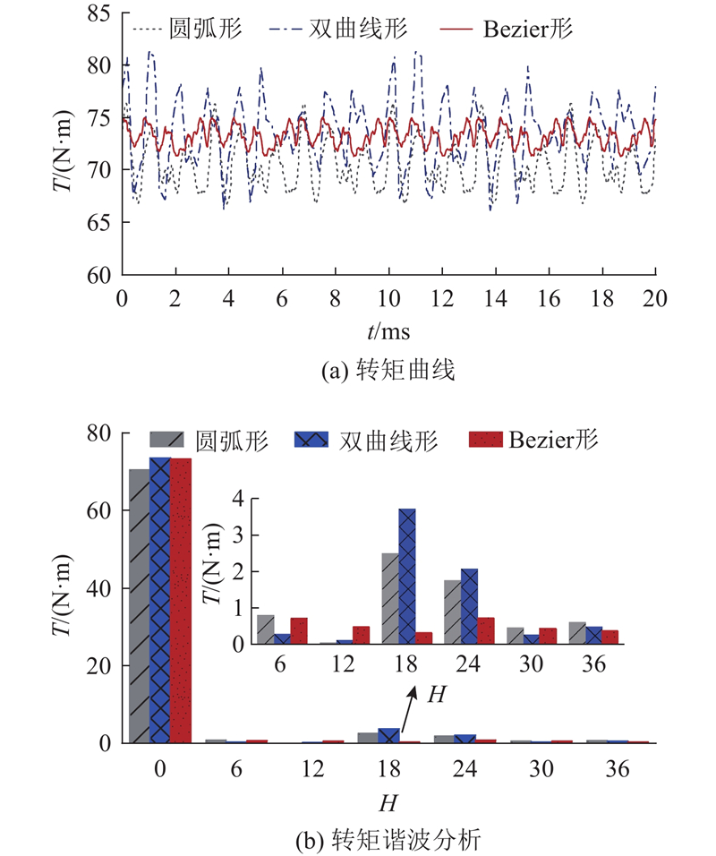
图 12 额定电流下3种转子结构的电机转矩及谐波分析
Fig.12 Motor torque and harmonic analysis of three rotor structures under rated current
表2中,Ld、Lq分别为d、q轴电感,
表 2 额定电流下3种转子结构的电机转矩性能
Tab.2
| 转子结构 | ||||
| 圆弧形 | 70.56 | 13.59 | 162.80 | 9.52 |
| 双曲线形 | 73.54 | 20.55 | 169.20 | 9.75 |
| Bezier形 | 73.26 | 5.06 | 168.90 | 8.55 |
如图13所示为不同电流下3种转子结构的电机电感及凸极比. 可知,非对称Bezier形转子结构的电机电感差在整体上优于圆弧形、双曲线形转子结构. 由于仅考虑电感差的提高,导致非对称Bezier形转子结构的电机凸极比上升较慢且整体降低.
图 13
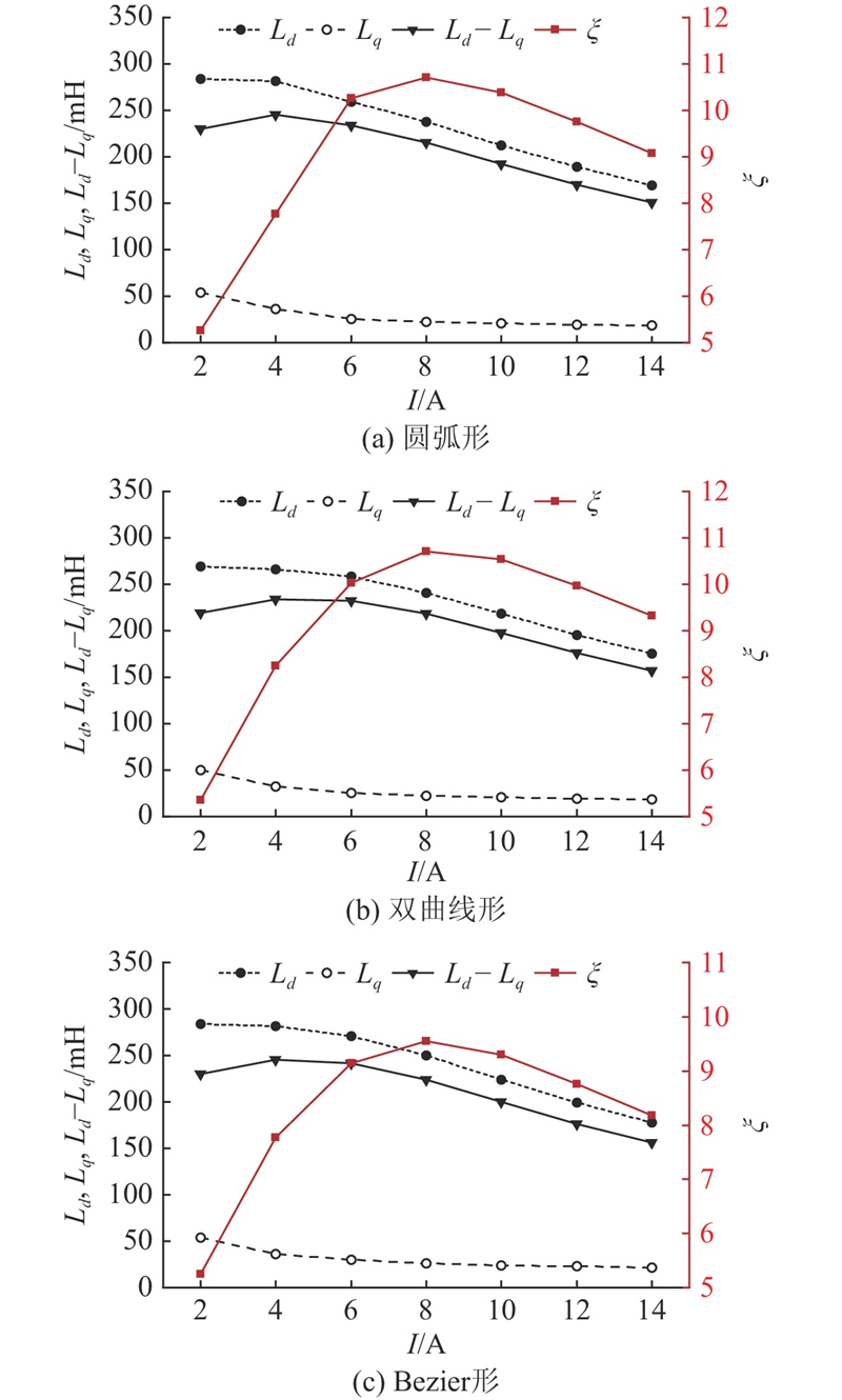
图 13 不同电流下3种转子结构的电机电感及凸极比
Fig.13 Inductance and salient pole ratio of motor with three rotor structures under different current
如图14所示为不同电流下3种转子结构的电机转矩性能. 可知,不同电流下非对称Bezier形转子结构的电机转矩脉动小于10%,较圆弧形、双曲线形明显降低.
图 14
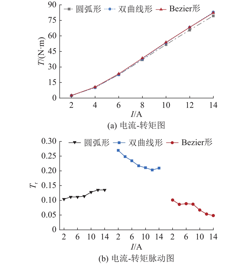
图 14 不同电流下3种转子结构的电机转矩性能
Fig.14 Torque performance of motor with three rotor structures under different current
如图15所示为不同电流下3种转子结构的电机功率因数
图 15
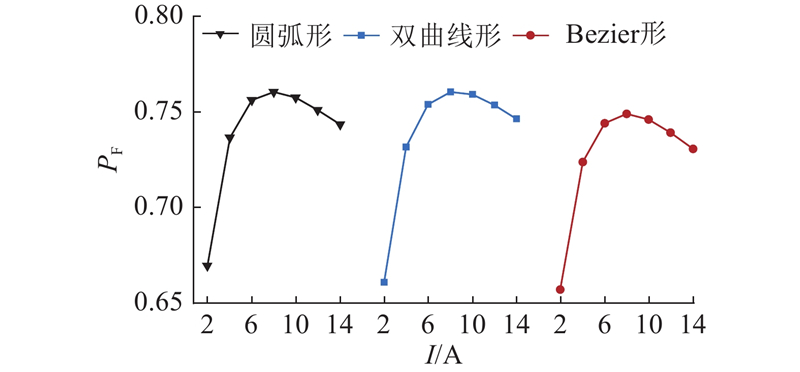
图 15 不同电流下3种转子结构的电机功率因数
Fig.15 Power factor of motor with three rotor structures under different current
如图16所示为不同电流角
图 16

图 16 不同电流角下3种转子结构的电机转矩性能
Fig.16 Torque performance of motor with three rotor structures at different current angle
综合电机输出转矩与转矩脉动性能考虑,非对称Bezier形转子较圆弧形、双曲线形转子结构有明显优势. 对于优化后的非对称Bezier形转子结构,须验证运行时的最大应力及机械强度是否符合要求.
图 17

图 17 稳态下圆弧形转子结构的应力及应变
Fig.17 Stress and strain of circular-shaped rotor structure under steady state
图 18
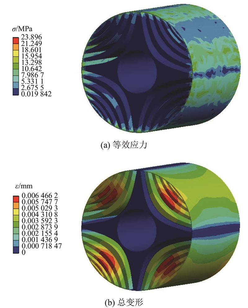
图 18 稳态下双曲线形转子结构的应力及应变
Fig.18 Stress and strain of hyperbolic-shaped rotor structure under steady state
图 19
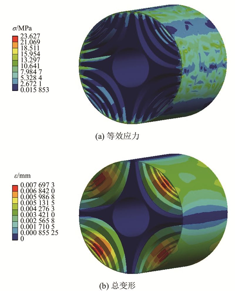
图 19 稳态下Bezier形转子结构的应力及应变
Fig.19 Stress and strain of Bezier-shaped rotor structure under steady state
为了进一步验证Bezier形转子结构的SynRM转矩性能,制造样机并搭建实验平台进行测试,如图20所示. 实验平台主要由主电路和控制电路2部分组成.
图 20
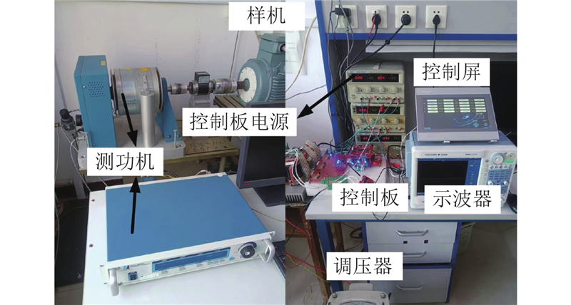
图 20 基于DSP的Bezier形转子的SynRM实验平台
Fig.20 Experiment platform of SynRM with Bezier-shaped rotor structure based on DSP
图 21
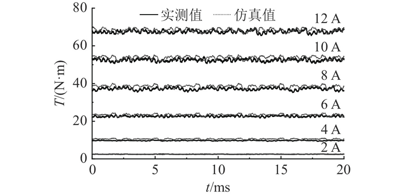
图 21 不同电流下Bezier形转子的SynRM转矩实验曲线
Fig.21 Experimental torque curve of SynRM with Bezier-shaped rotor under different current
表 3 不同电流下Bezier形转子的SynRM仿真与实验转矩性能
Tab.3
| 仿真值 | 实验值 | 仿真值 | 实验值 | ||
| 2 | 2.47 | 2.49 | 10.09 | 10.26 | |
| 4 | 10.55 | 9.72 | 8.61 | 8.95 | |
| 6 | 23.36 | 22.64 | 8.86 | 9.25 | |
| 8 | 38.52 | 37.14 | 8.69 | 9.13 | |
| 10 | 53.77 | 52.45 | 6.72 | 7.20 | |
| 12 | 68.30 | 67.52 | 5.33 | 6.25 | |
4. 结 论
(1)额定电流下,非对称Bezier形转子结构的电机高次转矩谐波含量低,较圆弧形、双曲线形转子结构的电机转矩脉动小. 在不同的电流及电流角下,综合考虑电机主要性能指标输出转矩和转矩脉动,非对称Bezier形转子结构较圆弧形、双曲线形转子结构有明显优势.
(2)非对称Bezier形转子结构的最大应力较圆弧形、双曲线形转子结构有所降低,且小于所用硅钢片材料的许用压力;最大应变与电机气隙长度相比可以忽略不计.
(3)通过样机实验,验证了非对称Bezier形转子结构优化设计方案的可行性,为SynRM及铁氧体辅助式SynRM的设计提供了新的选择,具有工程实用价值.
参考文献
Design and experimental performance assessment of an outer rotor PM-Assisted SynRM for the electric bike propulsion
[J].DOI:10.1109/TTE.2022.3202819 [本文引用: 1]
Battery supported solar water pumping system with adaptive feed-forward current estimation
[J].
Design optimization of a synchronous reluctance machine for high-performance applications
[J].DOI:10.1109/TIA.2021.3091416 [本文引用: 1]
Design optimization of synchronous reluctance motor for reducing iron loss and improving torque characteristics using topology optimization based on the level-set method
[J].
Design, optimisation and implementation of low-voltage synchronous reluctance motor for solar-powered systems
[J].DOI:10.1049/iet-pel.2018.5895 [本文引用: 1]
低转矩脉动同步磁阻电机磁障形状分析与优化设计
[J].
Flux barrier shape analysis and optimal design for low torque ripple synchronous reluctance machine
[J].
新型同步磁阻电机星形转子结构设计与分析
[J].
Astroid rotor structural design and analysis of a synchronous reluctance motor
[J].
A novel flux barrier parametrization for synchronous reluctance machines
[J].DOI:10.1109/TEC.2021.3099628 [本文引用: 1]
Synchronous reluctance machine optimization for high-speed applications
[J].DOI:10.1109/TEC.2018.2800536 [本文引用: 1]
Design optimization of transversely laminated synchronous reluctance machine for flywheel energy storage system using response surface methodology
[J].DOI:10.1109/TIE.2017.2716877 [本文引用: 1]
Magnetic field analysis of SynRel and PMASynRel machines with hyperbolic flux barriers using conformal mapping
[J].DOI:10.1109/TTE.2019.2959400 [本文引用: 1]
基于不对称转子结构与序贯田口稳健优化方法的同步磁阻电机设计
[J].
Synchronous reluctance machine based on asymmetrical rotor structure and sequential taguchi robust optimization method
[J].
Improvement of torque characteristics for a synchronous reluctance motor using MMA-based topology optimization method
[J].
FEAfix: FEA refinement of design equations for synchronous reluctance machines
[J].DOI:10.1109/TIA.2019.2954797 [本文引用: 1]
C- and circular-shaped barriers optimization in a synchronous reluctance rotor for torque ripples minimization
[J].
Application of epoxy resin in synchronous reluctance motors with fluid-shaped barriers for e-mobility
[J].DOI:10.1109/TIA.2021.3103826 [本文引用: 1]
Experimental verification of four-layer SynRM with asymmetric rotor structure in the stacking direction
[J].
Analytical method for optimal design of synchronous reluctance motor for electric scooter application
[J].
Snake optimizer: a novel meta-heuristic optimization algorithm
[J].DOI:10.1016/j.knosys.2022.108320 [本文引用: 1]
