

学者针对系统发电侧的惯量评估开展了诸多研究. Cao等[10]对发电侧惯量进行静态计算,认为发电侧惯量等于相同容量下所包含各发电机惯量的加权平均值;Guo等[11]基于加权最小二乘法对发电侧惯量进行静态计算. 上述研究计算发电侧惯量的前提是已知单个发电机的惯量,否则无法计算发电侧惯量. 基于发电侧动态响应,直接对发电侧惯量参数进行辨识的方法随后兴起. 该辨识方法主要分为1)基于暂态响应信号的惯量辨识方法,2)基于小扰动信号的惯量辨识方法. 方法1)通常先采用如切负荷或切机的操作激发系统有功频率暂态特性,再借助发电机转子运动方程完成辨识估计. Inoue等[12-14]结合发电机转子运动方程,利用频率测量数据和功率变化直接估计发电侧惯量. Wall等[15-16]提出的在线算法估计了系统扰动发生的时间及系统经过扰动事件后的惯量,该算法须连续在线处理有功功率和频率变化率的滑动窗数据. Del Giudice等[17]提出基于拓展卡尔曼滤波器的发电侧惯量估计方法,该方法必须在系统扰动发生的瞬间及时启动,否则会在惯量估计过程中引入较大误差. You等[18]基于机电波理论,推导出机电波传播速度与惯量成反比关系,通过计算系统各节点机电波的传播速度,给出美国东部电网的惯量分布图. 方法1)存在局限:大扰动的扰动事件会改变系统的运行工作点,影响系统安全稳定运行. 在方法2)方面,陈志杰等[19-21]根据电力系统运行时的频率变化情况,利用机器学习方法实现发电侧的惯量评估. 方法2)对历史数据的需求量大,须在已知的发电机惯量基础上迭代计算,较为复杂.
本研究利用同步相量测量单元(phase measurement unit, PMU)测量的机电振荡响应,提出基于小扰动下机电振荡参数的发电侧惯量评估方法. 1)基于各发电机与等值系统的惯量响应过程机理,推导在惯量响应结束时刻与各发电机惯量有关的不平衡功率分配公式,为求解系统中的发电侧惯量提供条件. 2)分析小扰动下发电机的机电振荡过程,得到系统特征方程的解与发电机功角振荡角频率的关系,利用韦达定理求取系统中各台发电侧的惯量,介绍单机系统发电侧惯量的计算方法. 3)在单机与多机系统仿真算例中验证所提评估方法的正确性.
1. 同步电机惯量与惯量响应过程
1.1. 同步电机惯量与等效惯量
忽略阻尼项,系统中第i台同步发电机的转子运动方程[22]为
式中:
当不附加频率控制的新能源发电设备接入系统时,会造成系统等效惯量
式中:
式中:
1.2. 同步电机惯量响应过程
当系统中出现扰动事件时,同步发电机组参与电网调频按时间顺序分为3个阶段:惯量响应阶段、一次调频阶段和二次调频阶段. 加入扰动类型为小扰动事件,一、二次调频一般不会发生动作,同步电机的频率变化特性主要由电机的惯量决定,意味着频率变化过程主要体现在惯量响应阶段,因此仅阐述同步电机的惯量响应过程. 当系统中有扰动事件发生时,会造成机械功率与电磁功率不平衡,此时同步电机的转子通过减速(加速)释放(吸收)旋转动能向系统中注入(吸收)有功功率,阻碍系统频率波动,这一阶段称为惯量响应阶段[23]. 由式(1)可知,频率变化与功角变化密切相关,本研究主要关注惯量响应过程中的功角变化过程,利用功角振荡曲线评估发电侧的惯量.
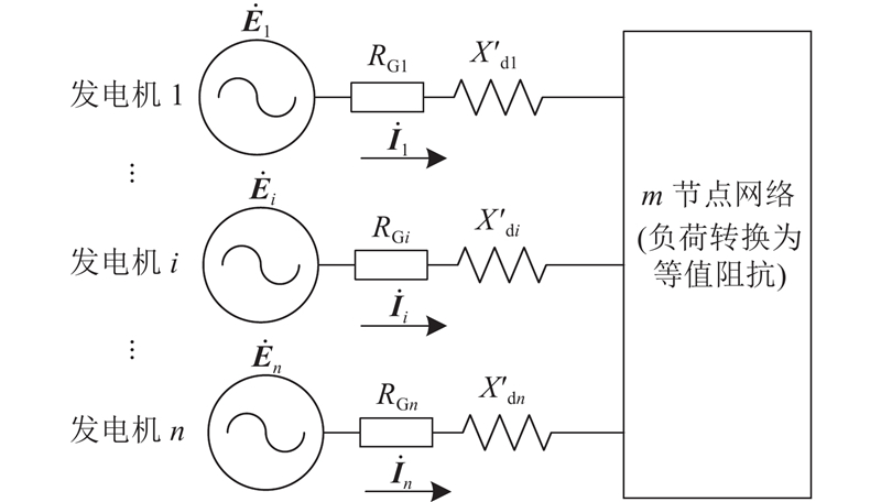
2. 多机系统的小信号状态方程
图 1
式中:
矩阵Y的元素
式中:
式中:
由于
定义
式中:
3. 发电机惯量评估方法
式(11)的特征值方程为
由式(12)可以得到
系统的特征方程表示为
将式(14)展开得到
式中:
其中
定义
将式(17)代入式(18),得到
当各台发电机转子的
定义惯量比为
联立求解式(16)和式(21),得到
式(22)是多机系统的各发电机惯量计算式. 计算各发电机惯量,关键是根据系统中各台发电机的有功功率曲线和功角振荡曲线求出惯量比ci和固有振荡频率
简单描述单机无穷大系统发电侧的惯量求取如下. 在单机无穷大系统,式(1)的增量方程[25]为
式中:
由式(24)可知,求取单机无穷大系统发电机的惯量,关键是根据功角振荡曲线求出固有振荡频率
4. 惯量比和固有振荡角频率的测量方法
同步PMU广泛应用于监测电力系统的动态过程[27-28],能够测量系统中各台发电机的有功功率曲线和功角振荡曲线. 假设在
依据式(21)得到惯量比
5. 仿真算例与结果分析
5.1. 单机无穷大系统仿真验证
图 2
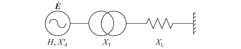
图 2 单机无穷大母线系统结构图
Fig.2 Structural diagram of single-machine infinite bus system
表 1 单机无穷大母线系统参数
Tab.1
| 参数 | 数值 | 参数 | 数值 | |
| 发电机内电势 | 0.9 | 线路电抗 | 0.15 | |
| 无穷大端电压 | 1.0 | 发电机功角 | 21.1 | |
| 发电机暂态电抗 | 0.3 | 发电机惯量 | 5 | |
| 变压器等效电抗 | 0.2 | — | — |
图 3
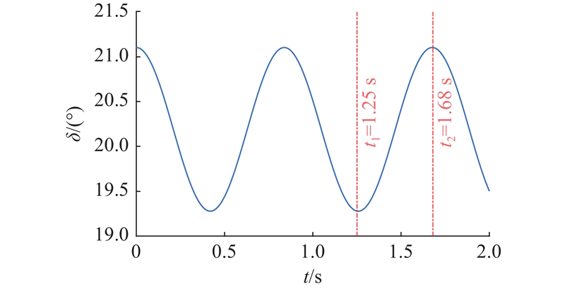
图 3 单机无穷大母线系统的功角振荡曲线
Fig.3 Power angle oscillation curve of single-machine infinite bus system
5.2. 双机互联系统仿真验证
图 4
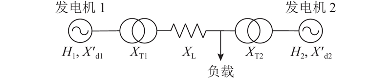
表 2 双机互联系统参数
Tab.2
| 参数 | 数值 | 参数 | 数值 | |
| 电机内电势 | 1.03 | 线路电抗 | 0.8 | |
| 电机暂态电抗 | 0.2 | 电机功角 | 5.60、−18.77 | |
| 变压器电抗 | 0.1 | 电机惯量 | 4、2 |
图 5
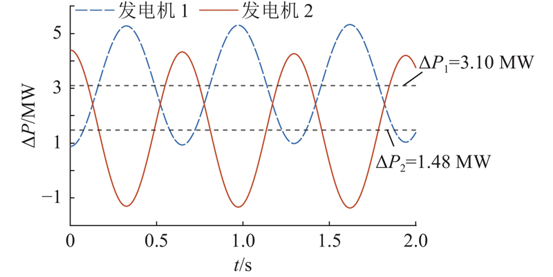
图 5 各发电机瞬时有功功率改变量曲线(双机互联系统)
Fig.5 Instantaneous active power change curve of each generator (dual-machine interconnection system)
图 6
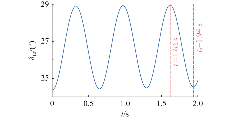
图 6 双机互联系统发电机相对功角曲线
Fig.6 Relative power angle curve between generators for dual-machine interconnection system
表 3 双机互联系统的发电机惯量评估结果
Tab.3
| 编号 | H/s | 误差/% | |
| 实际值 | 测量值 | ||
| 发电机1 | 4 | 4.24 | 6.00 |
| 发电机2 | 2 | 2.03 | 1.50 |
5.3. WSCC3机9节点系统仿真验证
图 7
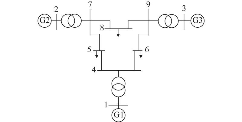
表 4 WSCC3机9节点系统的发电机参数
Tab.4
| 编号 | S/(MV·A) | H/s |
| 发电机1 | 247.5 | 23.64 |
| 发电机2 | 192.0 | 6.40 |
| 发电机3 | 128.0 | 3.01 |
图 8
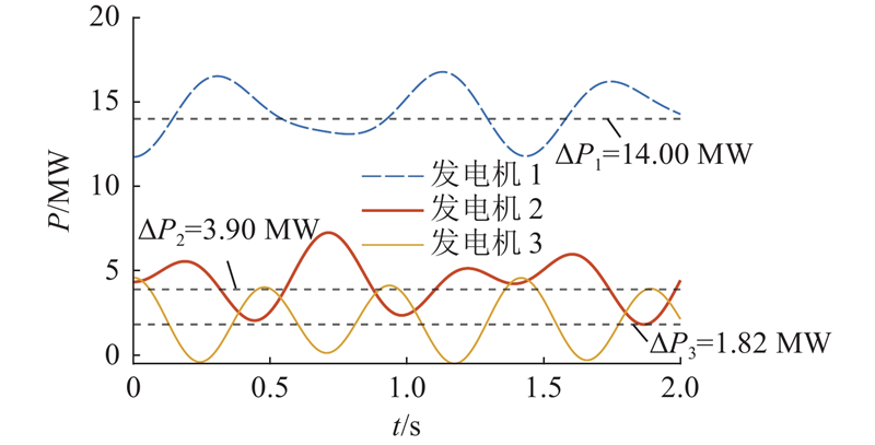
图 8 各发电机瞬时有功功率改变量曲线(WSCC3机9节点系统)
Fig.8 Instantaneous active power change curve of each generator (WSCC 3-machine 9-node system)
图 9
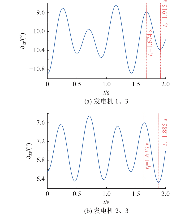
图 9 WSCC3机9节点系统发电机相对功角曲线
Fig.9 Relative power angle curve between generators for WSCC 3-machine 9-node system
表 5 WSCC3机9节点系统发电机惯量评估结果
Tab.5
| 编号 | H/s | 误差/% | |
| 实际值 | 测量值 | ||
| 发电机1 | 23.64 | 22.22 | 6.00 |
| 发电机2 | 6.40 | 6.18 | 3.44 |
| 发电机3 | 3.01 | 2.89 | 3.98 |
图 10
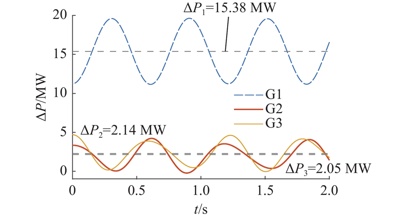
图 10 新能源接入后各发电机瞬时有功功率改变量曲线(WSCC3机9节点系统)
Fig.10 Instantaneous active power change curve of each generator after new energy connection (WSCC 3-machine 9-node system)
图 11
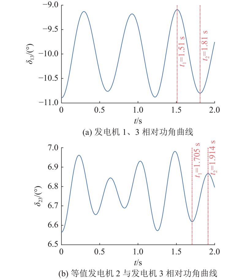
图 11 WSCC3机9节点系统发电机相对功角曲线(新能源接入后)
Fig.11 Relative power angle curve between generators for WSCC 3-machine 9-node system (after new energy connection)
表 6 新能源接入后WSCC3机9节点系统发电侧惯量评估结果
Tab.6
| 编号 | H/s | 误差/% | |
| 实际值 | 测量值 | ||
| 发电机1 | 23.64 | 22.20 | 6.09 |
| 等值发电机2 | 3.20 | 3.08 | 3.73 |
| 发电机3 | 3.01 | 2.96 | 1.66 |
5.4. 10机39节点系统仿真验证
在Matlab/Simulink平台搭建10机39节点系统,结构图如图12所示. 该系统有10台发电机、39条母线和19处负荷,系统详细信息参见文献[31]. 在5号发电机机组添加不附加频率控制的新能源发电设备,5号发电机等效惯量由式(4)计算得到. 各发电机以系统额定容量(1 000 MW)为基准的惯量如表7所示. 使节点39处的负荷有功功率突增300 MW(约为系统总负荷功率的5%),各发电机有功功率改变量
图 12
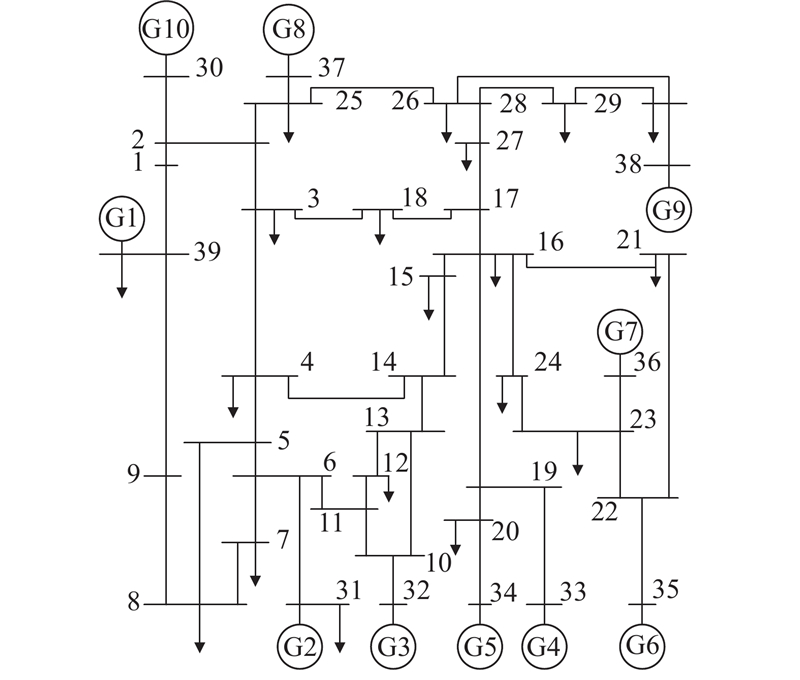
表 7 发电机或等效发电机惯量(10机39节点系统)
Tab.7
| 编号 | H/s | 编号 | H/s | |
| 发电机1 | 50.00 | 发电机6 | 3.48 | |
| 发电机2 | 3.03 | 发电机7 | 2.64 | |
| 发电机3 | 3.58 | 发电机8 | 2.43 | |
| 发电机4 | 2.86 | 发电机9 | 3.45 | |
| 发电机5 | 2.60 | 发电机10 | 4.20 |
表 8 各发电机或等效发电机有功功率改变量(10机39节点系统)
Tab.8
| 编号 | 编号 | |||
| 发电机1 | 189.00 | 发电机6 | 13.58 | |
| 发电机2 | 11.50 | 发电机7 | 10.20 | |
| 发电机3 | 13.06 | 发电机8 | 9.52 | |
| 发电机4 | 11.00 | 发电机9 | 13.56 | |
| 发电机5 | 10.55 | 发电机10 | 16.02 |
表 9 相对功角曲线振荡角频率(10机39节点系统)
Tab.9
| 编号 | |
| 发电机2-发电机1 | 3.918 |
| 发电机3-发电机1 | 4.124 |
| 发电机4-发电机1 | 4.126 |
| 发电机5-发电机1 | 4.124 |
| 发电机6-发电机1 | 4.124 |
| 发电机7-发电机1 | 4.122 |
| 发电机8-发电机1 | 4.608 |
| 发电机9-发电机1 | 4.123 |
| 发电机10-发电机1 | 4.124 |
表 10 10机39节点系统发电侧惯量评估结果
Tab.10
| 编号 | H/s | 误差/% | |
| 实际值 | 测量值 | ||
| 发电机1 | 50.00 | 46.83 | 6.34 |
| 发电机2 | 3.03 | 2.85 | 5.94 |
| 发电机3 | 3.58 | 3.24 | 9.50 |
| 发电机4 | 2.86 | 2.73 | 4.55 |
| 发电机5 | 2.60 | 2.61 | 0.38 |
| 发电机6 | 3.48 | 3.36 | 3.45 |
| 发电机7 | 2.64 | 2.53 | 4.17 |
| 发电机8 | 2.43 | 2.36 | 2.88 |
| 发电机9 | 3.45 | 3.36 | 2.61 |
| 发电机10 | 4.20 | 3.97 | 5.48 |
6. 结 语
本研究提出基于小扰动下机电振荡参数的发电侧惯量评估方法,在单机系统与多机系统仿真算例中验证了所提评估方法的正确性,为发电侧惯量优化配置提供了一定的理论基础. 1) 当系统中出现扰动时,各发电机先进入惯量响应阶段,各发电机的转子角速度变化率逐渐与系统等效角速度变化率相等,在惯量响应结束时刻,系统的不平衡功率分配与各发电机惯量有关. 2) 对于单机系统,通过单台发电机转子运动的增量方程可以得到发电侧惯量计算式,根据发电机功角振荡曲线求取固有振荡频率,得到单机无穷大系统的发电侧惯量. 3) 对于多机系统,通过多机系统的小信号状态方程与特征根的关系,结合惯量响应结束时刻与系统中各发电机惯量有关的不平衡功率分配公式得到发电侧惯量计算式. 根据发电机瞬时有功功率改变量曲线、相对功角振荡曲线得到惯量比与固有振荡频率,得到多机系统的发电侧惯量. 后续将深入研究计及新能源设备调频动态的发电侧惯量评估方法.
参考文献
含虚拟惯量的电力系统频率响应特性定量分析方法
[J].DOI:10.7500/AEPS20170605010 [本文引用: 1]
Quantitative analysis method of frequency response characteristics for power systems with virtual inertia
[J].DOI:10.7500/AEPS20170605010 [本文引用: 1]
高比例新能源接入下电力系统惯量相关问题研究综述
[J].
Review of research on power system inertia related issues in the context of high penetration of renewable power generation
[J].
Power system inertia estimation: review of methods and the impacts of converter-interfaced generations
[J].DOI:10.1016/j.ijepes.2021.107362 [本文引用: 1]
Challenges and opportunities of inertia estimation and forecasting in low-inertia power systems
[J].DOI:10.1016/j.rser.2021.111176 [本文引用: 1]
Inertia estimation based on observed electromechanical oscillation response for power systems
[J].
考虑频率分布特性的新能源电力系统等效惯量评估
[J].
Equivalent inertia assessment in renewable power system considering frequency distribution properties
[J].
Online identification of inertia distribution in normal operating power system
[J].DOI:10.1109/TPWRS.2020.2986721 [本文引用: 1]
计及不同控制方式的混合直流多馈入系统电网强度评估
[J].
Grid strength analysis of hybrid multi-infeed HVDC system considering different control modes
[J].
电力电子装置强风散热模型简化方法及应用
[J].
Simplification method and application of thermal model of forced air cooling system for power electronic device
[J].
Switching Markov Gaussian models for dynamic power system inertia estimation
[J].DOI:10.1109/TPWRS.2015.2501458 [本文引用: 1]
Adaptive parameter estimation of power system dynamic model using modal information
[J].DOI:10.1109/TPWRS.2014.2316916 [本文引用: 1]
Estimation of power system inertia constant and capacity of spinning-reserve support generators using measured frequency transients
[J].DOI:10.1109/59.574933 [本文引用: 1]
Online identification of power system equivalent inertia constant
[J].
Inertia estimation of the GB power system using synchrophasor measurements
[J].DOI:10.1109/TPWRS.2014.2333776 [本文引用: 1]
Simultaneous estimation of the time of disturbance and inertia in power systems
[J].DOI:10.1109/TPWRD.2014.2306062 [本文引用: 1]
Analysis of the sensitivity of extended Kalman filter-based inertia estimation method to the assumed time of disturbance
[J].DOI:10.3390/en12030483 [本文引用: 1]
Non-invasive identification of inertia distribution change in high renewable systems using distribution level PMU
[J].DOI:10.1109/TPWRS.2017.2713985 [本文引用: 1]
随机数据驱动下的两区域系统惯量估计
[J].
Two areas system inertia estimation based on ambient data
[J].
Estimation of power system inertia from ambient wide area measurements
[J].
Estimation of radial power system transfer path dynamic parameters using synchronized phasor data
[J].DOI:10.1109/TPWRS.2008.919315 [本文引用: 1]
考虑频率动态响应实时分区的电力系统惯量在线评估方法
[J].
Power system online inertia estimation considering real-time clustering of frequency dynamic response
[J].
电力系统频率动态中惯量与惯量响应特性辨析
[J].
Analysis on characteristics of inertia and inertial response in power system frequency dynamics
[J].
Frequency divider
[J].DOI:10.1109/TPEL.2016.2543222 [本文引用: 1]
面向新能源电力系统频率时空动态的节点等效惯量指标及其应用
[J].
Node equivalent inertia index for temporal-spatial frequency dynamics of renewable energy power system and its applications
[J].
基于断路器零阻抗特性的PMU量测状态估计方法
[J].DOI:10.3969/j.issn.1006-6047.2014.05.016 [本文引用: 1]
State estimation based on PMU measurements considering zero-impedance characteristics of circuit breaker
[J].DOI:10.3969/j.issn.1006-6047.2014.05.016 [本文引用: 1]
基于PMU同步测量的分区惯量估计方法
[J].
Area inertia estimation based on PMU synchronous measurements
[J].
考虑电网结构和参数的电力系统惯量分布特性
[J].DOI:10.7500/AEPS20201017005 [本文引用: 1]
Inertia distribution characteristics of power system considering structure and parameters of power grid
[J].DOI:10.7500/AEPS20201017005 [本文引用: 1]
On-line inertia estimation for synchronous and non-synchronous devices
[J].DOI:10.1109/TPWRS.2020.3037265 [本文引用: 1]
