

现代飞机制造主要采用模块化装配技术[1],全机各部件在部装生产线完成模块化制造与设备安装测试[2],最后在总装脉动生产线上完成大部件对接形成整机[3]. 对大型飞机而言,活动翼面种类与数量多、外形精度要求高、涉及的控制协调环节多、制造调试工作量大、安装调试流程复杂[4],对其偏转角度进行检测是机翼部装模块化装配的一个重要测试环节. 某重点机型活动翼面舵面种类数量多、结构复杂,传统翼面偏转角度检测方法传感器设备安装工作繁琐、所需机械夹具种类多尺寸大、工人操作耗时费力. 随着对各类高性能飞行器需求的不断增长,飞机制造企业的制造任务提升,生产线需要准确、快速且能够实时反映生产制造过程的活动翼面自动化检测操作系统来提升生产线效率并最终提高飞机产量.
本研究通过分析倾角传感器底层测量原理,考虑传感器系统误差、操作安装误差,参考已有的空间角度误差分析模型,改进适用于活动翼面绕水平轴偏转情景的空间角度双轴测量误差模型,并针对工况改进校准方法;以无线传输作为通信方式,搭建一整套活动翼面偏转测试系统,可以做到以数据、曲线、三维模型等可视化方式实时展示机翼活动翼面角度信息,偏转角度测量精度小于0.05°,采集频率高于10 Hz,可以满足实际测量需求.
1. 空间角度测量模型及误差分析
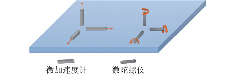
1.1. 基于微惯性系统的倾角传感器检测原理
图 1
如图2所示为基于电容原理的重力方向敏感器件示意图. 图中,
图 2

图 2 基于电容原理的重力加速度敏感器件示意图
Fig.2 Schematic diagram of gravity acceleration sensing device based on capacitance principle
如图3所示为3轴加速度计沿轴向检测重力加速度分量的示意图,各轴重力加速度分量与重力加速度之间的关系如下:
图 3

图 3 微加速度计测量三轴倾角
Fig.3 Measurement of three axis inclination angle with micro accelerometer
由于倾角传感器原理的限制,为了提高测量精度,在传统测试时对其安装准确性要求高. 当敏感轴与活动翼面转轴严格垂直时将得到最好的输出结果,相应的设备安装、调试难度较大,要求机翼上有划线之类的标识进行定位或专用工装夹具配合,对于大型翼面而言测试困难,操作麻烦,并且存在一定意外损伤翼面的风险.
1.2. 空间角度测量建模
根据活动翼面偏转测试实际工况需求以及过往对于单轴、双轴、三轴测量的研究,最符合本项目实际需求的是双轴测量. 本研究得出单轴测量的完整误差模型,对该误差模型进行分析并根据其结果合理简化双轴测量模型并给出实用的安装误差校准方法.
1.2.1. 单测量轴空间旋转模型
对于单轴倾角传感器而言,误差情形较简单. 在考虑初始误差的情况下得到实际的误差模型,根据误差参数项在模型中的作用针对性地提出校准方法.
图 4
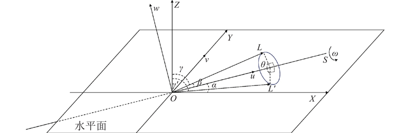
图 4 单轴倾角传感器空间测量模型
Fig.4 Spatial measurement model of single axis inclination sensor
在
同理可得,旋转轴
测量轴
当测量轴
测量轴
由倾角传感器的测量原理可知,测量轴
同理
得到传感器输出轴的表达式为
由式(11)、(12)可知,传感器的输出信号中包含前述2个安装误差
1.2.2. 双测量轴空间旋转模型推导与改进
对于双测量轴传感器,如果采用与单轴传感器类似的建模方法,初始时将存在4个误差参数,不利于后续的分析. 因此,本研究建模首先得到理想情况下无误差情形的双轴角度测量模型,然后将初始外部安装误差逐步考虑在内,对理想模型进行调整直至符合实际情况,得到求解模型,最后同样根据误差参数项在模型中的作用针对性地提出校准方法.
1)双测量轴空间旋转模型推导.
图 5
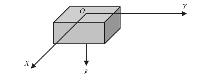
图 5 双轴传感器水平测量轴示意图
Fig.5 Schematic diagram of horizontal measurement axis of dual axis sensor
图 6
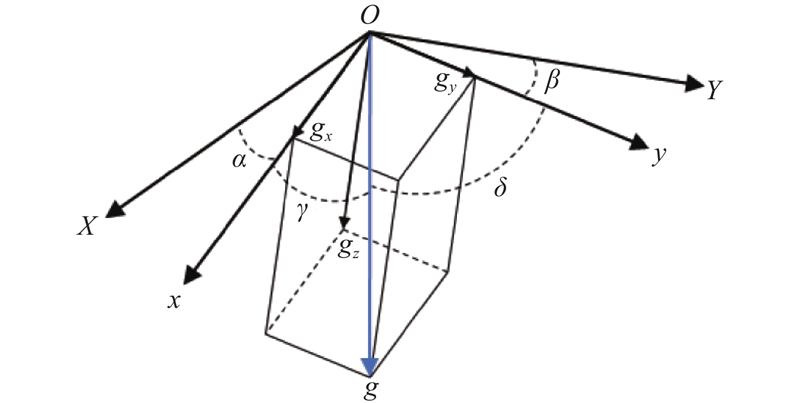
图 6 无安装误差状态下双轴测量原理示意图
Fig.6 Schematic diagram of dual axis measurement principle without installation error
根据如图6所示的几何关系,得到
由图可知
式(15)、(16)只是粗略给出了角度的加速度检测原理而不是坐标表示,将传感器在实际空间中随活动翼面旋转的过程纳入考虑后对上述原始角度的坐标表达进行理论分析建模如下[18].
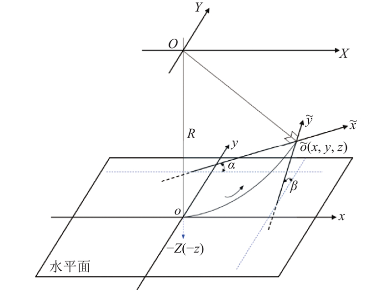
如图7所示为双轴空间倾角测量模型示意图,按照前文假设,倾角传感器的2个敏感轴已经严格垂直,只须考虑与理想轴不平行这个误差因素. 由于传感器测量目标角度是空间相对转角,与具体安装位置无关,假设传感器初始零位在水平面上的点
图 7
在无误差模型中将以下各点位置都在世界坐标系
图 8
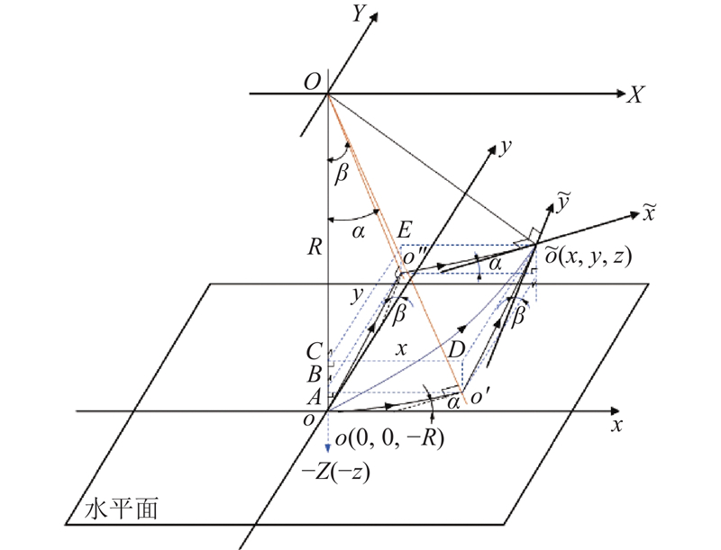
图 8 无误差情形下双轴倾角测量坐标求解过程示意图
Fig.8 Schematic diagram of coordinate solution process for dual axis inclination measurement without error
同理也可将传感器沿空间弧线
由于摆动过程中倾角传感器的旋转半径不变,有
综合式(17)~(19)可知,若知道点
下面讨论有误差情形下的双轴倾角测量模型. 存在误差说明双轴倾角传感器的2个测量轴都与理论水平轴存在一定未知夹角,同样以空间旋转中心点
图 9

依据无误差模型中已有的如式(17)~(19)所示的结论,可知有误差模型下测得的双轴倾角表达式为
因旋转半径不变,同样有
此时实际测得的偏角输出为
图 10
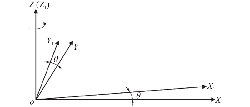
图 10 双轴无误差模型与有误差模型之间的关系
Fig.10 Relationship between biaxial models with and without error
根据空间坐标旋转理论,可知其旋转矩阵为
则有
可以得到
将式(17)、(18)、(20)、(21)代入式(25)后化简可得
式(26)为传感器测得的实际输出和理论偏角之间存在的关系,进一步可以求得
式(27)为适用于绕水平面内水平轴偏转的含误差双轴倾角传感器角度求解模型.
在实际检测过程中,由于安装产生了坐标系角度误差
对于式(28)、(29)中的任意一个而言,
式中:
2)双测量轴空间旋转模型改进.
虽然推导了双轴倾角测量模型并得到了空间偏转角度测量表达式,然而该误差模型对实际情形的简化较大. 如图10所示将双轴安装误差简化为传感器安装平面绕
图 11
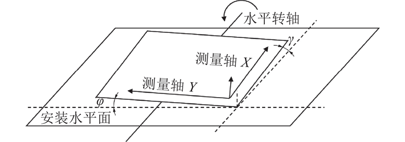
图 11 实际的双轴测量误差示意图
Fig.11 Schematic diagram of actual biaxial measurement error
为了解决上述问题,在考虑传感器存在绕垂直轴旋转误差的基础上,将与转轴平行的测量轴方向上(在图11中即为测量轴
图 12
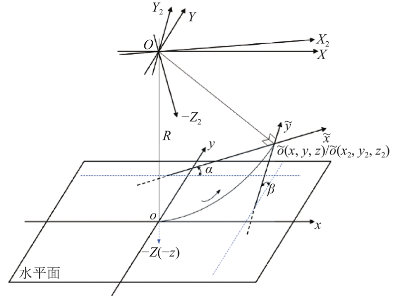
图 12 改进的双轴测量误差模型示意图
Fig.12 Schematic diagram of improved biaxial measurement error model
假设坐标系
可得
式中:
在实际单轴旋转测量中以
式(35)、(36)与式(28)、(29)所示的未改进前结果表达式类似,但原算法只用固定常量
同理,通过控制独立转台按一定规律运动使得理论倾角
式中:
2. 活动翼面偏转测试系统设计与实现
2.1. 系统整体架构
图 13
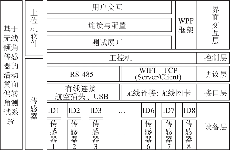
图 13 基于无线倾角传感器的活动翼面测试系统整体架构图
Fig.13 Overall architecture diagram of movable wing test system based on wireless inclination sensors
根据实际站位现场生产需求,该活动翼面偏转测试系统采用传感器精度为0.05°,系统通信通道为无线单通道,通讯协议为TCP/IP,传输角度信息速率为10 Hz,测试数据实时传输并以表格、曲线图、三维模型3种形式实时展示活动翼面位姿.
2.2. 硬件系统
根据实际需求,现场物理系统组成及实物图如图14所示. 该系统主要包括作为上位机的工控机、工业级路由器、用于串口通信的集线器以及下位传感器.
图 14

图 14 活动翼面偏转测试物理系统及无线组网图
Fig.14 Physical system and wireless network diagram of movable wing deflection test system
2.3. 软件系统
图 15
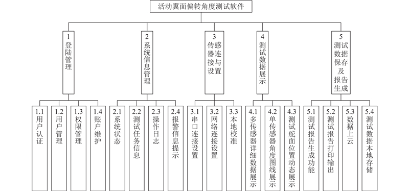
图 15 活动翼面偏转测试系统软件功能框架图
Fig.15 Software functional framework diagram of movable wing deflection test system
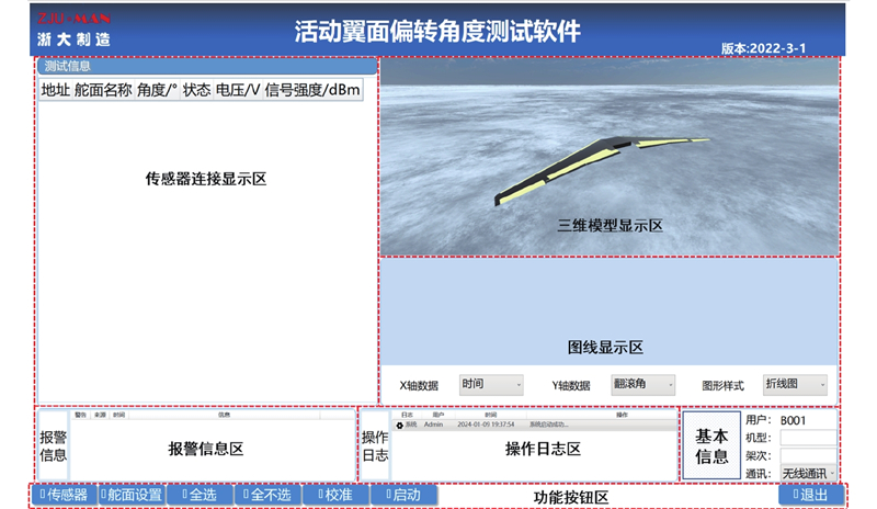
图 16
3. 现场测试及结果
3.1. 算法验证
使用的传感器是基于三轴加速度计的传感器,但使用场景中只有单轴空间旋转,因此在使用时根据实际需求,无意义轴不输出,只须对X轴、Y轴进行校准即可.
校准方法如1.2.2节所述,在转台控制单轴独立的情况下,即可对另一个轴进行高精度校准. 用于校准试验的三轴独立控制高精度转台来自中国航空工业集团有限公司北京精密机械研究所,分辨率为±0.0002°,转台及传感器安装如图17所示,校准测试实验如图18所示. 图中,右侧为转台控制台,外框代表Z轴保持不变,中框用于控制X轴基准(辅助轴),内框用于设置Y轴理论基准角度从而对Y轴(主测量轴)输出进行校准. 采用2个传感器分别进行实验,此时零漂、刻度因数误差已不再考虑,因此理论角度数据为0°时实测输出数据可设置为0°. 只对安装误差进行校准,获得的数据如表1~3所示,表中,
表 2 中框角度30°时传感器测量轴校准前后角度数据
Tab.2
| 0 | 0.39 | 0.00 | 0.39 | 0.00 |
| 30 | 30.34 | 30.00 | 0.34 | 0.00 |
| 60 | 60.20 | 59.99 | 0.20 | −0.01 |
| 0 | 0.39 | 0.00 | 0.39 | 0.00 |
| −30 | −29.66 | −29.99 | 0.34 | 0.01 |
| −60 | −59.77 | −59.96 | 0.23 | 0.04 |
图 17
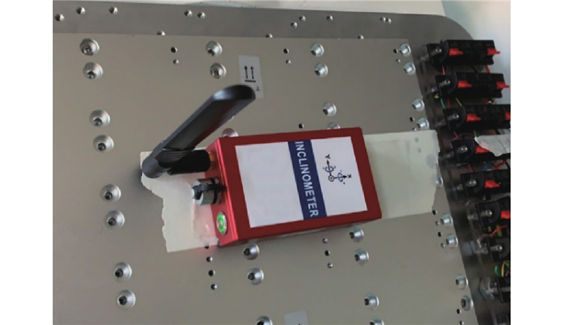
图 17 三轴独立控制的精密转台及传感器胶黏安装图
Fig.17 Installation drawing of three-axis independently controlled precision turntable and sensor adhesive
图 18
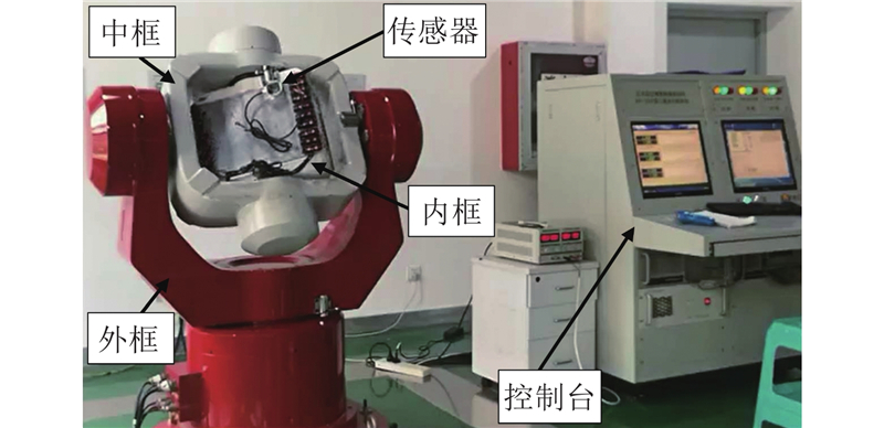
表 1 中框角度0°时传感器测量轴校准前后角度数据
Tab.1
| 0 | 0.00 | 0.00 | 0.00 | 0.00 |
| 30 | 30.01 | 30.01 | — | 0.01 |
| 60 | 59.98 | 59.98 | — | −0.02 |
| 0 | 0.00 | 0.00 | 0.00 | 0.00 |
| −30 | −29.99 | −29.99 | — | 0.01 |
| −60 | −59.95 | −59.95 | — | 0.05 |
表 3 中框角度60°时传感器测量轴校准前后角度数据
Tab.3
| 0 | 1.13 | 0.00 | 1.13 | 0.00 |
| 20 | 21.07 | 19.99 | 1.07 | −0.01 |
| 45 | 45.87 | 44.99 | 0.87 | −0.01 |
| 60 | 60.57 | 59.99 | 0.57 | −0.01 |
| 0 | 1.12 | 0.00 | 1.12 | 0.00 |
| −20 | −18.95 | −19.99 | 1.05 | 0.01 |
| −45 | −44.20 | −44.96 | 0.80 | 0.04 |
| −60 | −59.42 | −59.94 | 0.58 | 0.06 |
3.2. 现场测试
图 19
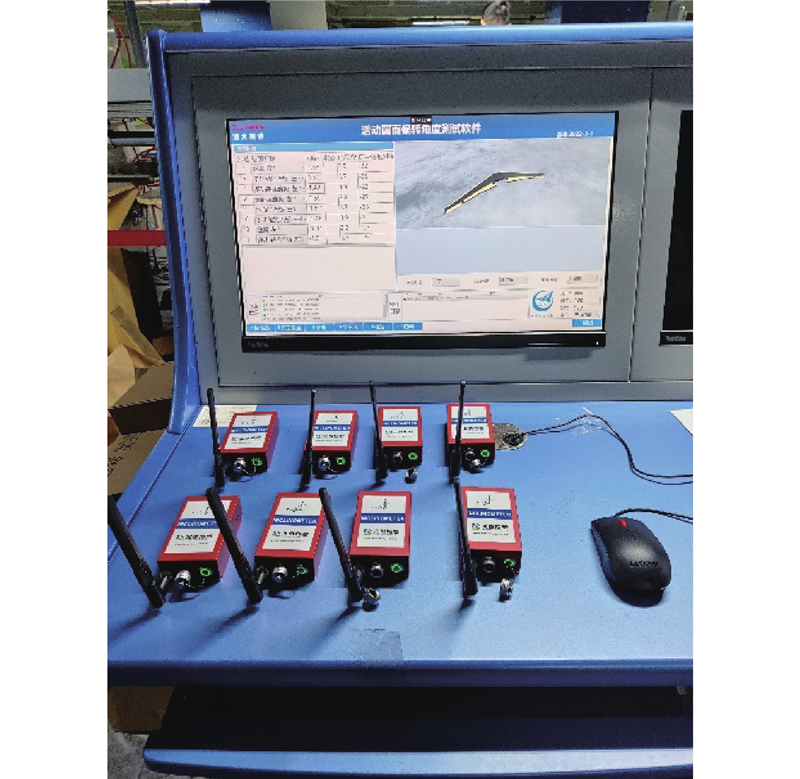
图 19 活动翼面偏转测试系统实物图
Fig.19 Physical diagram of movable wing surface deflection testing system
表 4 活动翼面偏转测试部分结果表
Tab.4
| 时间 | X/(°) | Y/(°) | U/V | S/dBm |
| 17:02:31 | −1.18 | −1.44 | 3.7 | −27 |
| 17:02:31 | −1.21 | −1.44 | 3.7 | −27 |
| 17:02:31 | −1.19 | −1.44 | 3.7 | −27 |
| 17:02:31 | −1.19 | −1.45 | 3.7 | −27 |
| 17:02:31 | −1.20 | −1.45 | 3.7 | −27 |
| 17:02:31 | −1.17 | −1.44 | 3.7 | −27 |
| 17:02:31 | −1.22 | −1.44 | 3.7 | −27 |
| 17:02:31 | −1.19 | −1.45 | 3.7 | −27 |
| 17:02:31 | −1.18 | −1.43 | 3.7 | −27 |
| 17:02:31 | −1.21 | −1.44 | 3.7 | −27 |
| 17:02:32 | −1.21 | −1.44 | 3.7 | −27 |
| 17:02:32 | −1.18 | −1.45 | 3.7 | −27 |
| 17:02:32 | −1.21 | −1.45 | 3.7 | −27 |
| 17:02:32 | −1.16 | −1.43 | 3.7 | −27 |
| 17:02:32 | −1.21 | −1.45 | 3.7 | −27 |
| 17:02:32 | −1.19 | −1.43 | 3.7 | −27 |
| 17:02:32 | −1.18 | −1.44 | 3.7 | −27 |
| 17:02:32 | −1.20 | −1.45 | 3.7 | −27 |
| 17:02:32 | −1.20 | −1.44 | 3.7 | −27 |
| 17:02:32 | −1.19 | −1.44 | 3.7 | −27 |
| 17:02:33 | −1.19 | −1.45 | 3.7 | −27 |
| 17:02:33 | −1.19 | −1.45 | 3.7 | −27 |
| 17:02:33 | −1.20 | −1.45 | 3.7 | −27 |
| 17:02:33 | −1.19 | −1.44 | 3.7 | −27 |
| 17:02:33 | −1.19 | −1.45 | 3.7 | −27 |
| 17:02:33 | −1.20 | −1.44 | 3.7 | −27 |
| 17:02:33 | −1.20 | −1.44 | 3.7 | −27 |
| 17:02:33 | −1.19 | −1.45 | 3.7 | −27 |
| 17:02:33 | −1.20 | −1.45 | 3.7 | −27 |
| 17:02:33 | −1.18 | −1.44 | 3.7 | −27 |
4. 结 论
(1)提出适用于活动翼面绕水平轴偏转情景下的双轴测量误差模型,在考虑机翼活动翼面偏转实际工况的情况下,引入新的误差变量来改进校准算法,使得传感器校准算法可以适应安装表面不平行的特殊工况. 经过校准的传感器角度输出精度得到提升,误差在允许范围内,满足机翼活动翼面角度的高精度测试需求.
(2)完成一套基于无线通讯协议的大飞机机翼活动翼面偏转测试系统的设计和实现,经过现场验证其可以达到任务目标. 较以往系统相比,本系统硬件安装不需要连接有线通讯线缆,操作简单,可以通过软件控制自动完成校准工作,且在无线网络下数据传输准确性、实时性也可以得到保证,能够显著提升现场活动翼面偏转测试的工作效率.
(3)本研究对空间角度的测量模型分析只考虑了安装误差,实际上各类误差之间也存在耦合,后续研究中可以尝试对系统各类误差进行整体识别,来提高校准模型的测量精度.
参考文献
波音787飞机总装配线及其特点
[J].
Boeing 787 final assembly line and its characteristics
[J].
飞机总装站位式生产线的综合测试技术研究
[J].
Research on integrative testing of movable stations final assembly line of airplanes
[J].
飞机脉动总装智能生产线构建技术
[J].
Construction technologies of intelligent pulse production line for aircraft final assembly
[J].
Large-scale spatial angle measurement and the pointing error analysis
[J].DOI:10.1007/s11801-016-6028-z [本文引用: 1]
基于激光位移传感器的面角度测量技术研究
[J].
Study on the plane angle measurement technology based on laser displacement sensors
[J].
基于双目视觉的飞机活动翼面偏角测量研究
[J].
Deflection angle measurement of aircraft rudder based on binocular vision
[J].
Optical measurement techniques for mobile and large-scale dimensional metrology
[J].
大空间坐标尺寸测量研究的现状与发展
[J].
Status and development of large-scale coordinate measurement research
[J].
基于光电伺服平台的动态角度测量方法研究
[J].
Research on dynamic angle measurement method based on electro-optical servo platform
[J].
Automatic measurement in large-scale space with the laser theodolite and vision guiding technology
[J].
A novel single-axis mems tilt sensor with a high sensitivity in the measurement range from 0° to 360°
[J].DOI:10.3390/s18020346 [本文引用: 1]
An improved calibration technique for mems accelerometer-based inclinometers
[J].DOI:10.3390/s20020452 [本文引用: 1]
采用倾角传感器实现空间旋转角度测量的解析方法研究
[J].DOI:10.7652/xjtuxb201310019 [本文引用: 1]
Analytical approach for measurement of spatial angle with inclination sensor
[J].DOI:10.7652/xjtuxb201310019 [本文引用: 1]
Survey on internet of things (IoT) for different industry environments
[J].DOI:10.33166/AETiC.2019.03.004 [本文引用: 1]
