

水泵是现代工业的关键部件,应用于农业、水利工程、海水淡化、核电、化工等众多领域[1-4]. 其中,离心泵以结构简单、体积小、体积流量稳定、成本低等优点,占据超过70%的市场份额[5]. 为了解决传统离心泵中存在的流体泄露问题,屏蔽泵采用磁力耦合,通过电机与泵的集成设计,成功实现了液体的无泄漏传输[6]. 不过在高速工况下,机械轴承容易发生碰撞变形,无法满足安全运行的要求. 磁悬浮轴承可以代替机械轴承实现无接触运行,但系统过长的轴向尺寸限制了临界转速的提高[7]. 无轴承永磁薄片电机(bearingless permanent magnetic slice motor,BPMSM)根据磁轴承与定子结构的相似性,将磁轴承结构集成到电机定子结构中,实现自驱动、自悬浮. 以离心泵为负载的BPMSM系统具有无润滑、零磨损、效率高、免维护等优点[8],在储能、压缩机、人工血泵、化工密封泵、生物工艺泵等众多产品中广泛应用[9-13].
针对以上不足,本研究致力于探究离心泵水力激振力对电机悬浮性能的影响. 采用虚位移法构建电机的悬浮力数学模型,并通过有限元方法进行验证,针对高速工况下的转子不稳定运行问题,采用转子磁场定向矢量策略进行控制,最后借助CFD软件模拟离心泵内部流场,分析高速磁悬浮离心泵叶轮转子在水力激振力作用下的动力学特性,获得可靠约束叶轮径向偏移的方法.
1. 结构及工作原理
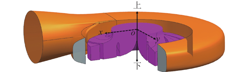
图 1
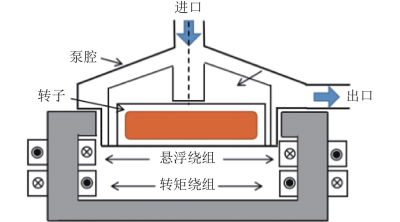
图 1 磁悬浮无轴离心泵结构图
Fig.1 Structure schematic of magnetic suspension bearingless centrifugal pump
图 2
2. 数值模型
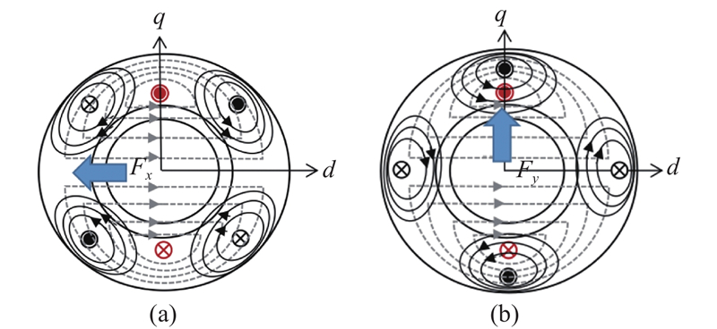
2.1. 电机径向悬浮力数学模型
在转子偏心情况下,电机径向悬浮力可以依据磁场虚位移理论求得,在实际运行时,还须将电机偏心后受到的单边磁拉力考虑在内,即
式中:
2.2. 控制系统
磁悬浮无轴离心泵的控制系统如图3所示. 图中,
图 3
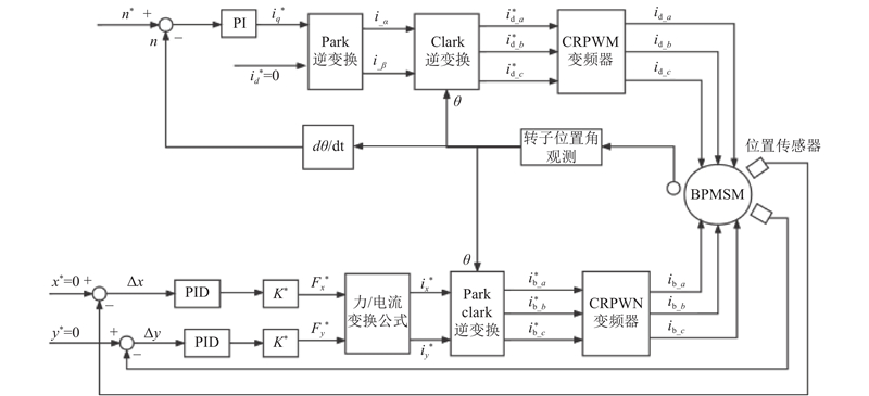
图 3 磁悬浮无轴离心泵的控制系统
Fig.3 Controlling system in magnetic suspension bearingless centrifugal pump system
对于悬浮系统,通过传感器识别转子径向位置,并与理想值
2.3. 离心泵模型
设计比转速
表 1 离心泵结构设计参数
Tab.1
| 结构参数 | 变量 | 数值 |
| 叶片数 | Z | 6 |
| 叶轮进口直径 | | 36 |
| 叶片出口角 | | 25 |
| 叶轮出口直径 | | 70 |
| 叶片包角 | | 120 |
| 叶轮出口宽度 | | 10 |
| 泵进口直径 | | 40 |
| 蜗壳基圆直径 | | 78 |
| 泵出口直径 | | 36 |
| 蜗壳出口宽度 | | 18 |
2.3.1. 控制方程
离心泵内部流场是一个三维、具有非均匀空间分布的瞬态流场. 输送介质为清水,可以将其视为不可压缩流体处理,考虑不可压缩流动的连续性方程和雷诺时均Navier-Stokes (N-S)方程表达式[20]分别如下:
式中:
为了封闭雷诺时均N-S方程,采用应用最为广泛、稳定性最高的标准
式中:
2.3.2. 仿真设置
离心泵的水力模型和网络造型如图4所示. 本研究采用有限体积法并借助ANSYS CFX软件求解离心泵内部流体的质量、动量守恒方程,选用标准
图 4
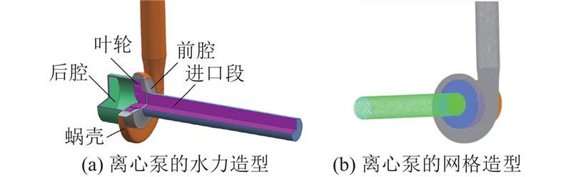
图 4 离心泵的水力模型与网格造型
Fig.4 Hydraulic model and mesh modeling of centrifugal pumps
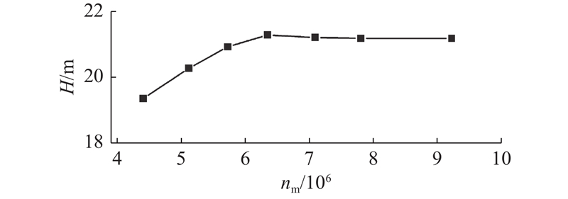
在ANSYS ICEM软件中进行网格划分,在确保网格质量的前提下,共设置7组网格造型进行网格无关性分析,如图5所示. 图中,nm为网格数. 当总网格数大于634万,扬程变化幅值小于1%时,可以忽略网格差异对扬程的影响. 为了节约计算资源,最终确定网格总数为634万.
图 5
3. 结果与分析
3.1. 电机有限元仿真结果
借助ANSYS对额定功率2 kW,转速6000 r/min,极对数
表 2 电机结构设计参数
Tab.2
| 结构参数 | 变量 | 数值 |
| 定子外径 | | 170 |
| 气隙长度 | | 4 |
| 定子内径 | | 76 |
| 转子外径 | | 68 |
| 永磁体厚度 | | 4 |
| 转子内径 | | 30 |
| 转矩绕组匝数 | | 120 |
| 转子轴长 | | 30 |
| 悬浮绕组匝数 | | 120 |
图 6
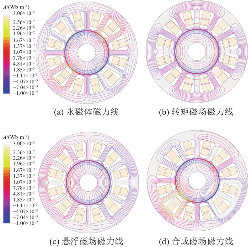
表 3 有限元仿真与理论计算的总悬浮力对比结果
Tab.3
| I/A | F1/N | F2/N | e0/% |
| 1 | 32.61 | 31.69 | 4.04 |
| 2 | 65.22 | 62.59 | 4.06 |
| 3 | 97.81 | 92.16 | 5.71 |
| 4 | 130.41 | 120.02 | 7.82 |
| 5 | 163.02 | 148.07 | 8.93 |
| 6 | 195.62 | 169.96 | 12.80 |
图 7
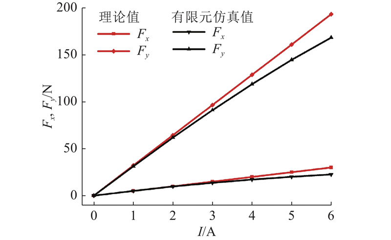
图 7 有限元仿真与理论计算的悬浮分力对比结果图
Fig.7 Comparison of component suspension force between finite element simulation and theoretical calculation
3.2. 离心泵径向水力激振力仿真结果
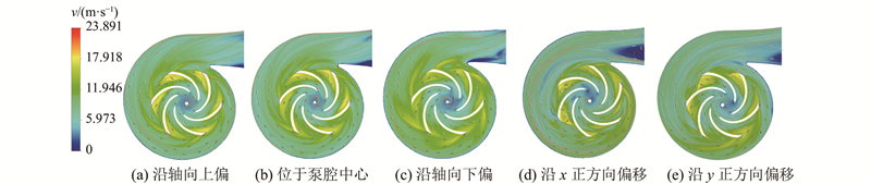
叶轮转子悬浮于泵腔的非中心位置,会对系统的悬浮性能产生影响,因此有必要探究不同位置处叶轮受到的径向水力激振力. 在泵几何结构参数不变的前提下,改变叶轮在泵腔中的初始位置,设置5组方案:沿径向x正方向偏移3 mm、沿径向y正方向偏移3 mm、叶轮处于泵腔中心、沿轴向上偏移3 mm、沿轴向下偏移6 mm,如图8所示. 其中,设计沿轴向下偏移6 mm的方案是为了更大程度模拟水流对叶轮的冲击作用. 在设计工况体积流量
图 8
3.2.1. 流场分析
如图9所示为离心泵水平截面的流速分布图. 可以看出,在叶轮轴向偏移的3种方案中,向下偏移方案的流场效果最差,在叶片尾缘处存在低速尾流区,在靠近隔舌处流态紊乱且开始出现漩涡现象;在叶轮径向偏移的2种方案中,沿x正方向偏移方案的流场效果较差,在叶轮出口处产生大量涡旋,在蜗壳出口段速度梯度变化大,脱流严重. 分析原因可知,叶轮沿x轴正向偏移,即叶轮与进口管中心发生偏离,会导致进入叶轮的体积流量分布不均,叶轮各流道内流体流速不均,流体经叶轮高速运转后产生较大离心现象,从而造成涡流;流体经过蜗壳隔舌后,流速分布变化较大,压力梯度增大,导致出口处产生流动分离.
图 9
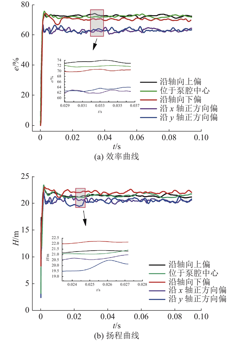
3.2.2. 外特性分析
如图10所示为模型泵效率e、扬程H曲线图. 可以看出,叶轮径向偏移方案的效率、扬程均低于轴向偏移方案的,叶轮沿
图 10
3.2.3. 径向水力激振力分析
图 11
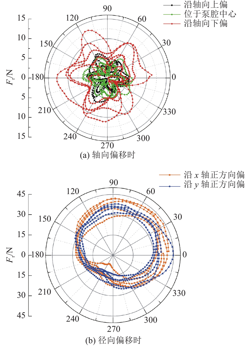
图 11
叶轮径向水力激振力
Fig.11 Time-domain distribution of radial flow-induced forces Fr of impeller
图 13
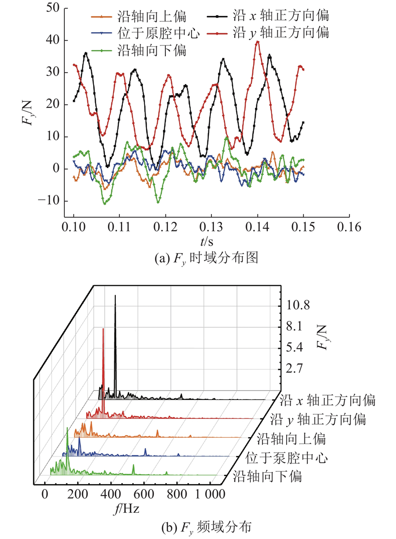
图 13
叶轮径向水力激振力分量
Fig.13 Time-frequency domain distribution of radial flow-induced force Fy of impeller
图 12
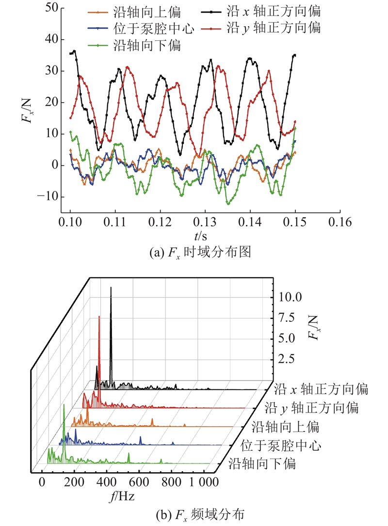
图 12
叶轮径向水力激振力分量
Fig.12 Time-frequency domain distribution of radial flow-induced force Fx of impeller
为了最大程度探究离心泵在变频调速时叶轮受到的水力激振力,选取前文研究中流动效果最差的叶轮位置偏移(即沿
图 14

图 14 不同转速下离心泵的效率、径向力分布图
Fig.14 Distribution of efficiency and radial force at different rotation speeds
3.2.4. 不同转速下离心泵水力特性分析
为了进一步探究磁悬浮无轴离心泵的悬浮性能,选取最大径向水力激振力方案,即沿
3.3. 电机悬浮控制仿真
依照如图3所示的控制思路,在Matlab/Simulink环境下搭建磁悬浮无轴离心泵的运动控制系统. 其中,悬浮模块添加了叶轮的径向水力振力60 N,以探究系统悬浮性能的可靠性. 仿真采用变步长ode23tb,总时间0.6 s,额定转速
图 15
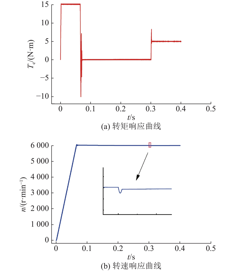
图 15 系统转矩、转速响应曲线
Fig.15 Time histories of torque and rotation speed of impeller
图 16
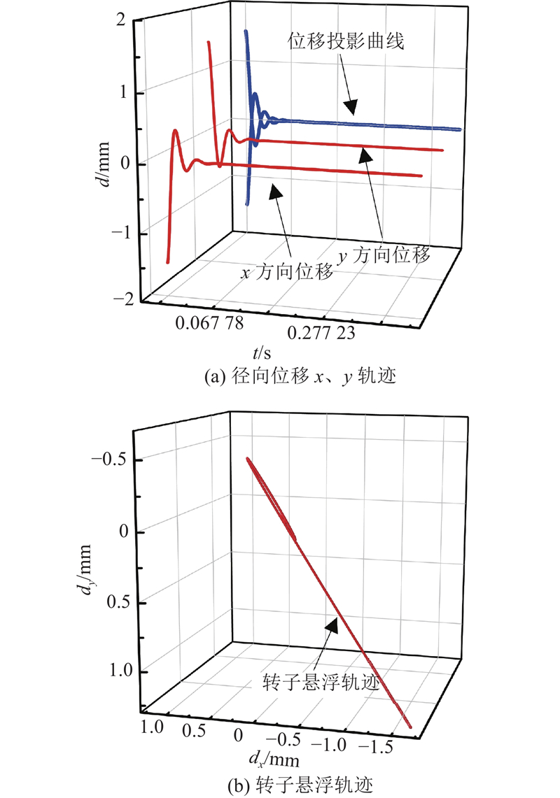
图 16 未加载离心泵时系统径向位移仿真结果
Fig.16 Simulation results of radial displacement of system with centrifugal pump not loaded
图 17
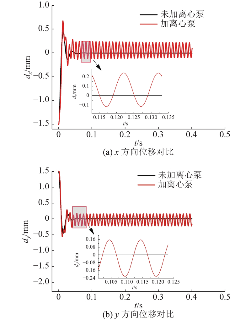
图 17 加载离心泵时系统径向位移仿真结果
Fig.17 Simulation results of radial displacement of system with centrifugal pump loaded
如图15所示为系统转矩、转速响应曲线. 图中,Te为转矩. 可以看出,经过0.1 s,BPMSM便能达到额定转速6000 r/min,该过程基本无超调,在
4. 结 论
(1) 在所设置的5组叶轮偏移方案中,叶轮沿径向x方向偏移时流场效果最差,叶轮及蜗壳出口段速度梯度大,脱流严重,同时还伴随漩涡、回流问题.
(2) 由5组叶轮偏移方案的对比可知,叶轮径向布置方案的效率最低(约63%),比叶轮居中布置方案效率下降约7%.
(3) 分析3组不同转速工况下的运行方案,可以看出,随着转速的升高,叶轮径向水力激振力不断增大,离心泵运行效率不断降低.
(4) 在所构建的控制系统中,BPMSM启动时间短、响应速度快,转矩突变对电机影响较小(约1%),系统抗干扰性能好.
(5) 当BPMSM加载最大水力激振力60 N后,转子的径向偏移小于250 μm,远远小于电机气隙4 mm,可见本研究所构建的磁悬浮无轴离心泵系统具有较好的悬浮运行特性,可靠性高.
(6) 本研究的工作均以数值模拟的方式进行,为了验证仿真结果的正确性,后续研究应制作样机,并开展相关实验研究.
参考文献
Correlation research of rotor-stator interaction and shafting vibration in a mixed-flow pump
[J].
Experimental study on cavitation characteristics of mixed-flow pump during startup
[J].
Fluid-structure interaction study of a mixed-flow pump impeller during startup
[J].
Energy performance and flow patterns of a mixed-flow pump with different tip clearance sizes
[J].
CFD and energy loss model analysis of high-speed centrifugal pump with low specific speed
[J].
屏蔽泵冷却循环回路热流耦合
[J].
Thermal-fluid coupling of cooling cycle loop in canned-motor pump
[J].
高速无轴承永磁电机设计与分析
[J].DOI:10.3969/j.issn.1673-6540.2017.12.018 [本文引用: 1]
Design and analysis of high-speed bearingless permanent magnet motors
[J].DOI:10.3969/j.issn.1673-6540.2017.12.018 [本文引用: 1]
Design and implementation of a novel interior permanent magnet bearingless slice motor
[J].DOI:10.1109/TIA.2021.3080663 [本文引用: 1]
Ultra-high temperature (250 ℃) bearingless permanent magnet pump for aggressive fluids
[J].DOI:10.1109/TMECH.2017.2729618 [本文引用: 1]
A 300 000 r/min magnetically levitated reaction wheel demonstrator
[J].
Modeling and characteristic investigation of axial reluctance force for bearingless switched reluctance motor
[J].
Review of bearingless synchronous motors: principle and topology
[J].
Performance analysis of suspension force and torque in an IBPMSM With V-Shaped PMs for flywheel batteries
[J].
新型双绕组无轴承磁通切换永磁电机的设计与分析
[J].
Design and analysis of novel double-winding bearingless flux-switching permanent magnet machine
[J].
Suspension performance analysis on the novel hybrid stator type bearingless switched reluctance motor
[J].DOI:10.1109/TMAG.2021.3077923 [本文引用: 1]
The influence of impeller geometries on hemolysis in bearingless centrifugal pumps
[J].DOI:10.1109/OJEMB.2020.3037507 [本文引用: 1]
Hysteresis bearingless slice motors with homopolar flux-biasing
[J].DOI:10.1109/TMECH.2017.2740429 [本文引用: 1]
Optimization design of bearingless permanent-magnet slice motor
[J].
Optimization design of bearingless synchronous reluctance motor
[J].
Investigation on inner flow quality assessment of centrifugal pump based on Euler head and entropy production analysis
[J].
