

本文通过波形钢腹板的均匀化和截面转换,将波形钢腹板混凝土梁理想化为夹心梁,然后基于混合能变分原理,引入Zig-zag位移和横向应力假设,推导波形钢腹板混凝土梁动力问题的控制方程,求出不同边界条件下的自振频率及其振型,并将其与其他结果进行对比分析,验证本文方法的有效性.
1. 波形钢腹板梁及其夹芯梁模型
图 1
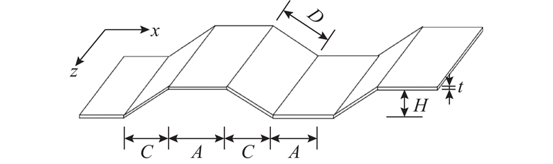
图 1 波形钢腹板(CSW)的几何形状
Fig.1 Geometric configuration of corrugated steel web (CSW)
图 2
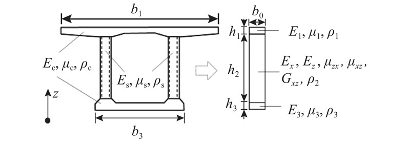
将上、下混凝土板转换为宽度为b0的各向同性层,其等效的材料特性为
式中:Ei为第i层转换后的弹性模量,μi为第i层转换后的泊松比,ρi为第i层转换后的密度,并有b0=1 m.
设x轴为梁的轴线方向,z轴为梁的高度方向,参照Johnson等[15]的研究,波形钢腹板可均匀化为正交各向异性材料,Ex、Ez为均匀化后的弹性模量,μxz、μzx为均匀化后的泊松比,Gxz为均匀化后的剪切模量,ρ2为均匀化后的密度:
式中:A、C、D、H为波形钢腹板的几何尺寸,具体如图1中所示.
2. 平面问题自由振动的混合能变分原理
对于
式中:Dij为材料常数. 对于混凝土顶底板,简化为各向同性材料,矩阵D中的非零元素为
对于波形钢腹板等效成正交各向异性的中间层,矩阵D中的非零元素为
自由振动可用如下的泛函极值问题[16]表示
式中:ω为自由振动频率,
其中,Ω为梁所占的平面区域.
通过Legendre变换,最大应变能
式中:下标逗号表示对紧跟后面的坐标求导数. 式(9)中的应力和位移是独立的自变函数,因此非常适合于在层合结构中独立地对应力和位移作出尽可能反应实际情况的分布假设.
至此,平面问题的自由振动转化为如下的泛函极值问题:
3. 波形钢腹板梁自由振动的Zig-zag理论
3.1. 位移和应力假设
由于波形钢腹板梁的混凝土顶底板与波形钢腹板的轴向刚度相差较大,经典梁理论中的平截面假定与实际相差甚远,采用Zig-zag位移假设. 引入新的位移量s表示轴向位移的弯折程度[13],即
式中:k=1,2,3;
横向切应力可独立地假设为
式中:
一般地,
式中:
另外,对于梁的振动,挠度产生的动能占主要部分,因此式(8)可简化为
式中:
3.2. 自由振动控制方程
把式(11)和(13)中的位移和应力代入式(14)中的混合能表达式,完成
以及本构关系:
以及2个辅助方程:
根据上、下表面边界条件,应有τ0=τ3=0. 其中P为引入的新位移量s所对应的内力,同时M与
3.3. 用位移表示的控制方程
联立式(16)~(21),消去其他物理量后,可得只包含挠度w的常微分方程:
式中:bii(i=1,2,3,4,5)是与波形钢腹板梁的几何尺寸和材料参数有关的常数,定义如下:
其中,
其中,kij(i=1,2,3,4,5;j=1,2,3)是与波形钢腹板梁的几何参数和材料参数有关的常数,详见附录A.
其他物理量也可用挠度w表示. 联立式(16)~(21),通过积分和化简可得由挠度w表示的位移及内力表达式.
式中:
轴向位移u为
式中:
同样地,可以得到用挠度w表示的内力
式中:
4. 频率与振型
4.1. 两端简支波形钢腹板梁的振动频率
对于两端简支边界条件,可设振型为
式中:
引入
式中:α和β是由于引入Zig-zig位移模式带来的与材料参数及几何尺寸相关的参数,而
式中:
式中:
式(45)与Xu等[17]得出的自振频率表达形式一致.
为了验证本文公式,以一实际波形钢腹板梁为例,总高度为2.5 m,其中混凝土顶板和底板的厚度均为250 mm,跨径为45 m,顶板宽为25 m,底板宽为15 m. 混凝土的弹性模量为34.5 GPa,泊松比0.2,密度为2 400 kg/m3,波形钢腹板材料的弹性模量为200 GPa,泊松比为0.3,密度为7 850 kg/m3. 另外设波形钢腹板的几何参数为A=430 mm、C=370 mm、D=430 mm、H=220 mm、t=16 mm. 换算时取b0 = 1 m,那么换算后的材料参数如下:混凝土顶板E1=862.5 GPa、μ1=0.2、ρ1=60 000 kg/m3,波形钢腹板D11=15.7 MPa、D22=6.88 GPa、D12=4.72 GPa、D33=2.29 Gpa、ρ2=270.04 kg/m3,混凝土底板E3=517.5 GPa、μ3=0.2、ρ3=36 000 kg/m3. 所得自振频率如表1所示,其中n为频率阶数,f为自振频率,δ为相对误差.
表 1 简支(SS)波形钢腹板(CSW)梁自振频率
Tab.1
| n | f/Hz | δ/% | f/Hz | δ/% | |
| 有限元 | 本文方法 | 经典梁理论 | |||
| 1 | 17.191 | 17.218 | 0.16 | 19.950 | 16.05 |
| 2 | 51.768 | 51.904 | 0.26 | 79.800 | 54.15 |
| 3 | 88.945 | 89.264 | 0.36 | 179.550 | 101.90 |
| 4 | 126.248 | 126.572 | 0.26 | 319.200 | 152.80 |
| 5 | 162.577 | 163.840 | 0.78 | 498.749 | 206.80 |
| 6 | 199.196 | 201.377 | 1.10 | 718.199 | 260.50 |
| 7 | 235.990 | 239.461 | 1.47 | 977.549 | 314.20 |
| 8 | 273.130 | 278.316 | 1.90 | 1 276.800 | 367.50 |
基于ABAQUS软件,采用八节点平面应力单元,上、下混凝土板的单元尺寸均为0.025 m×0.450 m,波形钢腹板层的单元尺寸为0.200 m×0.450 m,建立波形钢腹板梁的平面应力有限元模型以计算其动力特性. 从表1可以看出,Zig-zag梁理论所得自振频率与有限元结果基本吻合,而经典梁理论所得结果的误差随频率阶数迅速增加. 采用本文方法求得的前8阶自振频率与有限元结果的误差均小于2%,表明本文方法可精确地预测波形钢腹板梁的自由振动频率. 而经典梁理论的误差则要大得多,第1阶频率的误差就已经超过15%,高阶频率的误差更是迅速增加. 韦忠瑄等[8]曾引入修正系数以减少误差,但也只能改善基频的预测精度.
4.2. 其他边界条件下的振动频率
式(22)的通解可写为
式中:
其中,±
工程中常见的边界条件一般为简支、固支和自由3种,分别为
将通解代入式(48)~(50)可得关于待定系数ci的线性齐次方程组:
式中:
式(52)就是波形钢腹板梁自由振动的特征方程,是一个关于频率的超越方程,通过数值求解,即可得到不同边界条件下的振动频率.
再次考虑等4.1节中的波形钢腹板梁. 针对两端简支(SS)情形,式(52)获得的频率与式(44)的结果(见表1)完全一致. 这是由于在两端简支情形下,式(46)的一般解退化为如式(38)所示的解.
表 2 两端固支(CC)波形钢腹板梁自振频率
Tab.2
| n | f/Hz | δ/% | f/Hz | δ/% | |
| 有限元 | 本文方法 | 经典梁理论 | |||
| 1 | 27.665 | 27.708 | 0.16 | 45.224 | 63.47 |
| 2 | 58.502 | 58.737 | 0.40 | 124.663 | 113.10 |
| 3 | 93.965 | 94.475 | 0.54 | 244.388 | 160.10 |
| 4 | 130.414 | 131.375 | 0.74 | 403.989 | 209.80 |
| 5 | 167.346 | 168.981 | 0.98 | 603.490 | 260.60 |
| 6 | 204.474 | 207.107 | 1.29 | 842.891 | 312.20 |
| 7 | 241.953 | 245.946 | 1.65 | 1 122.180 | 363.80 |
| 8 | 279.834 | 286.625 | 2.07 | 1 441.400 | 415.10 |
表 3 固支-简支(CS)波形钢腹板梁自振频率
Tab.3
| n | f/Hz | δ/% | f/Hz | δ/% | |
| 有限元 | 本文方法 | 经典梁理论 | |||
| 1 | 22.435 | 22.473 | 0.17 | 31.166 | 38.91 |
| 2 | 55.357 | 55.537 | 0.33 | 100.997 | 82.45 |
| 3 | 91.464 | 91.880 | 0.46 | 210.723 | 130.40 |
| 4 | 128.171 | 128.980 | 0.63 | 360.348 | 181.10 |
| 5 | 164.940 | 166.390 | 0.88 | 549.874 | 233.40 |
| 6 | 201.835 | 204.220 | 1.18 | 779.299 | 286.10 |
| 7 | 238.937 | 242.671 | 1.56 | 1 048.61 | 338.90 |
| 8 | 276.454 | 281.931 | 1.98 | 1 357.84 | 391.20 |
表 4 固支-自由(CF)波形钢腹板梁自振频率
Tab.4
| n | f/Hz | δ/% | f/Hz | δ/% | |
| 有限元 | 本文方法 | 经典梁理论 | |||
| 1 | 6.593 | 6.599 | 0.10 | 7.107 | 7.80 |
| 2 | 30.762 | 30.913 | 0.49 | 44.539 | 44.79 |
| 3 | 67.243 | 67.647 | 0.60 | 124.713 | 85.47 |
| 4 | 104.546 | 105.350 | 0.77 | 244.384 | 133.70 |
| 5 | 142.189 | 143.544 | 0.95 | 403.989 | 184.10 |
| 6 | 179.391 | 181.642 | 1.26 | 603.490 | 236.40 |
| 7 | 216.701 | 220.171 | 1.60 | 842.890 | 289.00 |
| 8 | 254.029 | 259.211 | 2.04 | 1 122.180 | 341.80 |
4.3. 振型
图 3

5. 结 语
本文基于平面问题自由振动的混合能变分原理,通过假设Zig-zag形式的轴向位移和分层二次抛物线分布的横向切应力,建立了波形钢腹板梁自由振动的Zig-zag理论,给出了不同边界条件下的频率和振型的控制方程. 数值结果表明,相比经典梁理论,提出的Zig-zag理论能精确地计算波形钢腹板梁的振动频率及其振型,频率的误差随振动阶数的增加非常缓慢,适用于需要求解高阶频率的情形. 同时,经典梁理论高估了波形钢腹板梁的抗弯刚度,计算得到的振动频率远高于实际值,需要引起注意.
值得指出的是,该理论的横向切应力满足上、下表面为0以及层间连续条件,因此与一般的高阶梁理论(如Timoshenko梁理论)不同,无须引入剪切修正系数.
参考文献
波形钢腹板PC箱梁桥应用综述
[J].DOI:10.3969/j.issn.1002-0268.2005.07.011 [本文引用: 1]
Summary of application of prestressed concrete box-girder bridges with corrugated steel webs
[J].DOI:10.3969/j.issn.1002-0268.2005.07.011 [本文引用: 1]
Prestressed concrete girder bridges with corrugated steel webs: review
[J].
The mechanics of composite corrugated structures: a review with applications in morphing aircraft
[J].DOI:10.1016/j.compstruct.2015.07.099 [本文引用: 1]
Accordion effect of prestressed steel beams with corrugated webs
[J].
Refined nonlinear finite element modelling towards ultimate bending moment calculation for concrete composite beams under negative moment
[J].DOI:10.1016/j.tws.2017.02.011 [本文引用: 1]
Flexural vibration of prestressed concrete bridges with corrugated steel webs
[J].DOI:10.1142/S0219455417500237 [本文引用: 1]
Experimental and analytical studies of innovative prestressed concrete box-girder bridges
[J].DOI:10.1007/BF02479523 [本文引用: 1]
波形钢腹PC组合箱梁的动力特性研究
[J].
Study on dynamic properties of the prestressed concrete box-girder with corrugated steel webs
[J].
Historical review of Zig-zag theories for multilayered plates and shells
[J].DOI:10.1115/1.1557614 [本文引用: 1]
On a general theory of anisotropic shells
[J].DOI:10.1016/0021-8928(58)90108-4 [本文引用: 1]
On a certain mixed variational theorem and a proposed application
[J].DOI:10.1002/(ISSN)1097-0207 [本文引用: 1]
On a mixed variational theorem and on shear deformable plate theory
[J].
Laminated composite plate theory with improved in-plane responses
[J].DOI:10.1115/1.3171828 [本文引用: 2]
Two-dimensional analytical solutions of simply supported composite beams with interlayer slips
[J].DOI:10.1016/j.ijsolstr.2006.04.027 [本文引用: 1]
Corrugated webs in plate girders for bridges
[J].DOI:10.1680/istbu.1997.29305 [本文引用: 1]
Static, dynamic, and buckling analysis of partial interaction composite members using Timoshenko's beam theory
[J].DOI:10.1016/j.ijmecsci.2007.02.006 [本文引用: 1]
