|
|
|
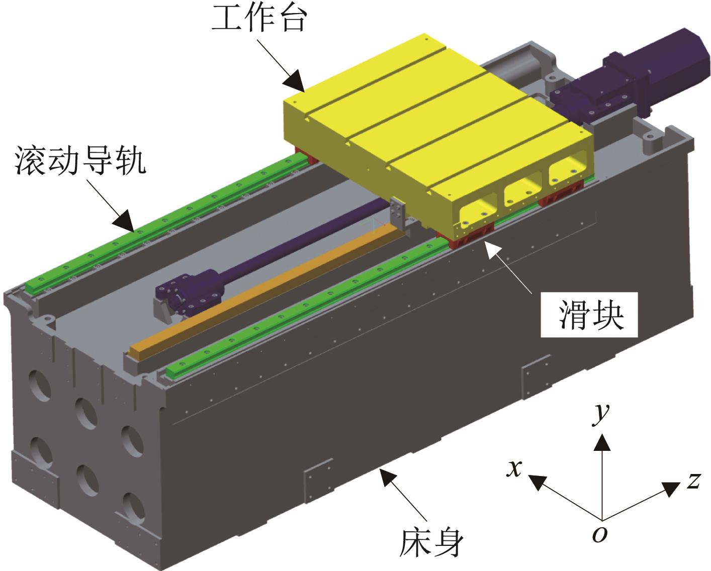
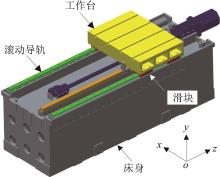
Fig.1 Linear feed system with double guide rails and four sliders
|
|
|
|
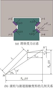
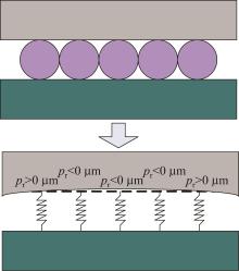
Fig.2 Single slider mechanical model
|
|
|
|
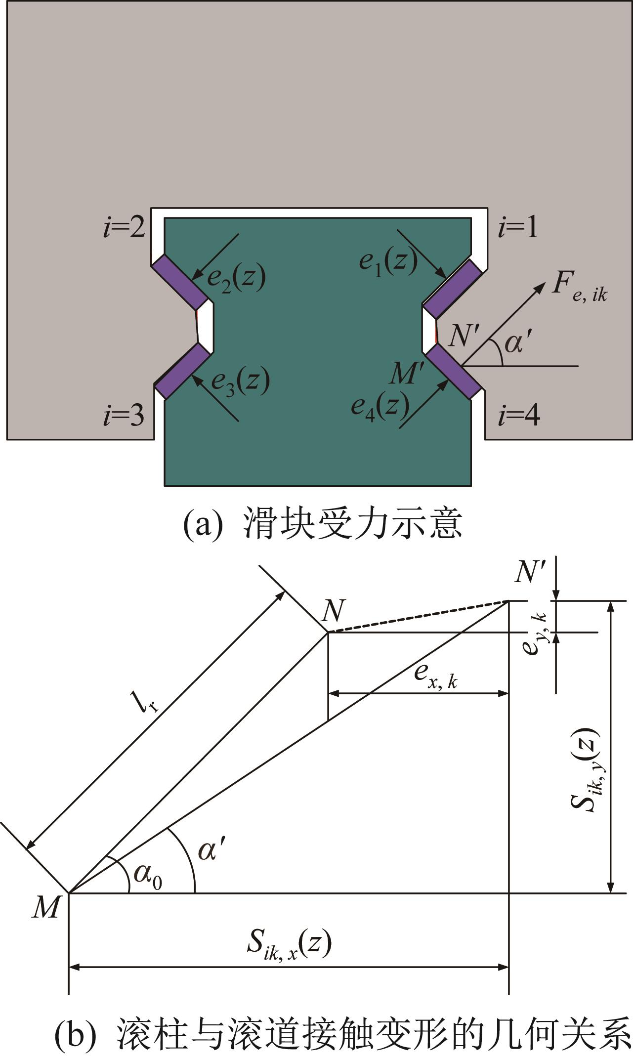
Fig.3 Force analysis of slider under the action of geometric error of guide rail
|
|
|
|
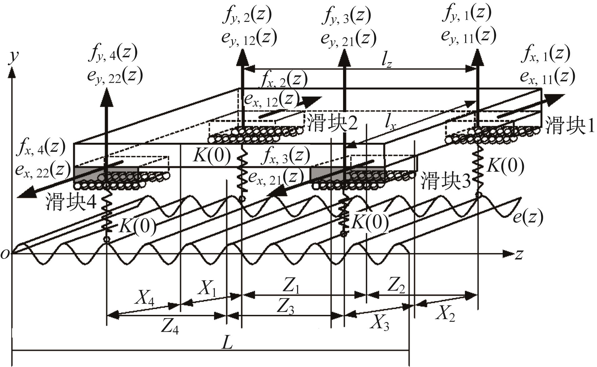
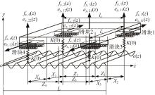
Fig.4 Static balance model of linear feed system with double guide rails and four sliders
|
|

|
|
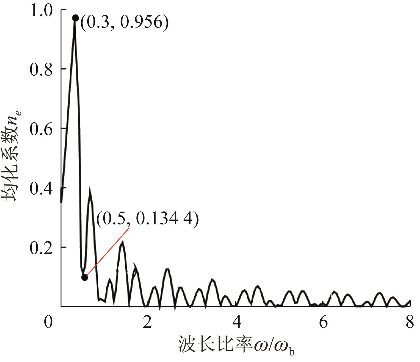
Fig.5 Effect of wavelength of guide rail geometric error on error averaging coefficient of workbench straightness error
|
|

|
|
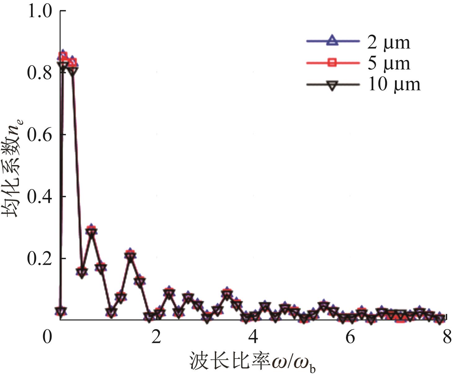
Fig.6 Effect of amplitude of guide rail geometric error on error averaging coefficient of workbench straightness error
|
|
| 参数 | 导轨和滑块 | 工作台 |
|---|
| 材料 | 马氏体不锈钢 | QT500 | | 密度/(g/cm3) | 7.75 | 7.0 | | 弹性模量/GPa | 206 | 162 | | 泊松比 | 0.3 | 0.293 |
|
|
Table 1 Material attribute setting for single slider finite element model
|
|
|
|
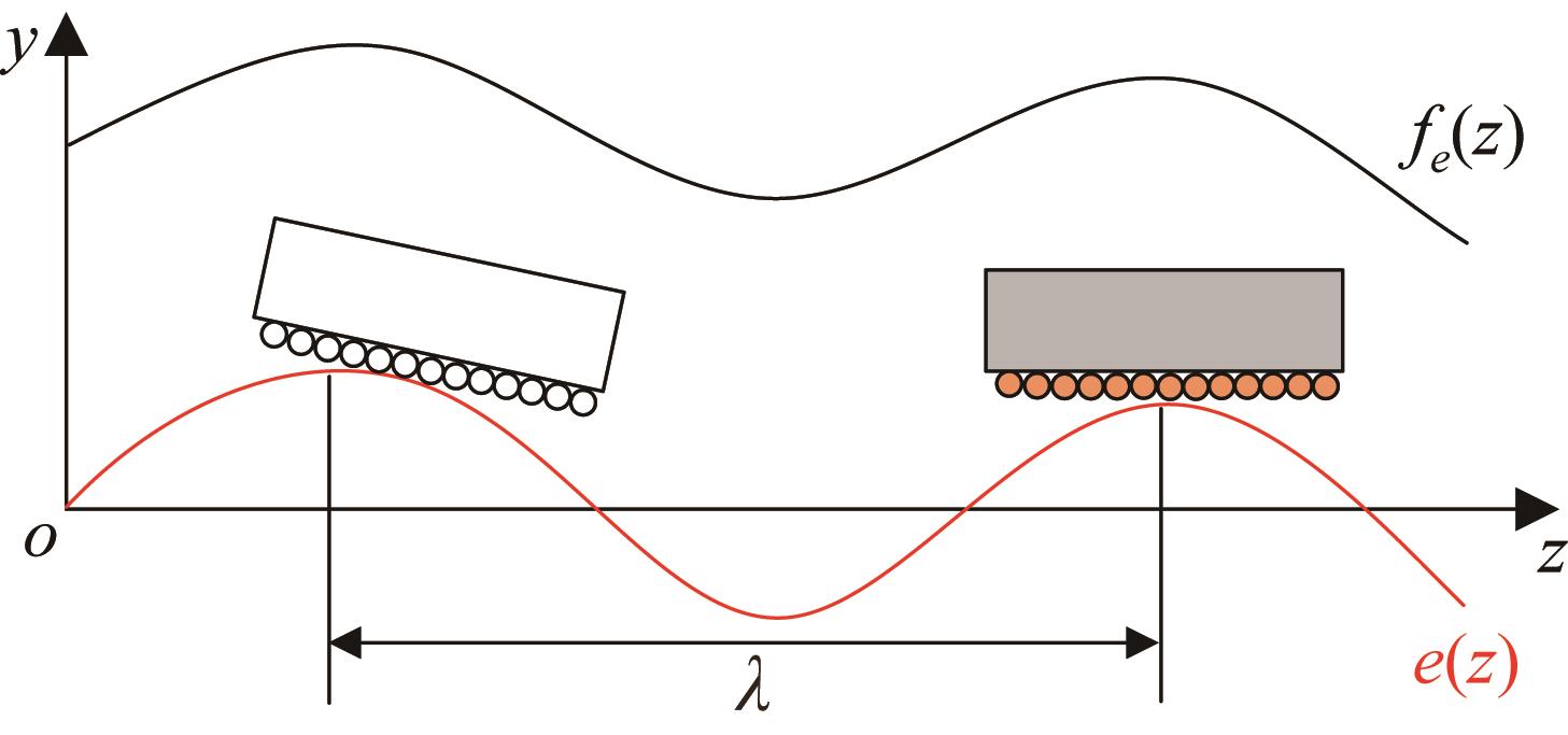
Fig.7 Mapping relationship between roller pre-tightening and geometric error of guide rail
|
|
|
|
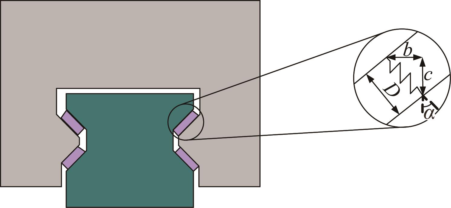
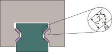
Fig.8 Geometric relationship of contact between roller and raceway surface
|
|

|
|
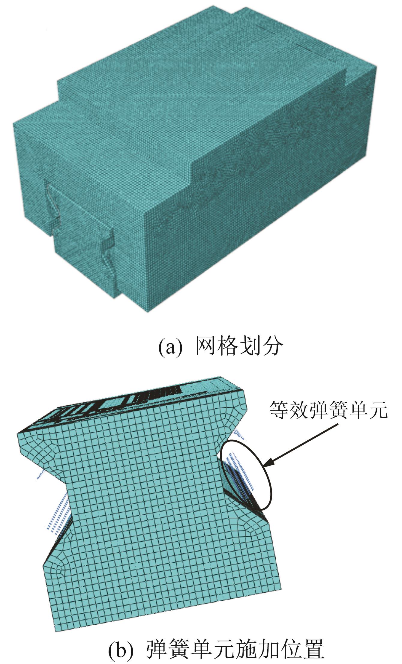
Fig.9 Single slider finite element model based on spring element method
|
|
|
|
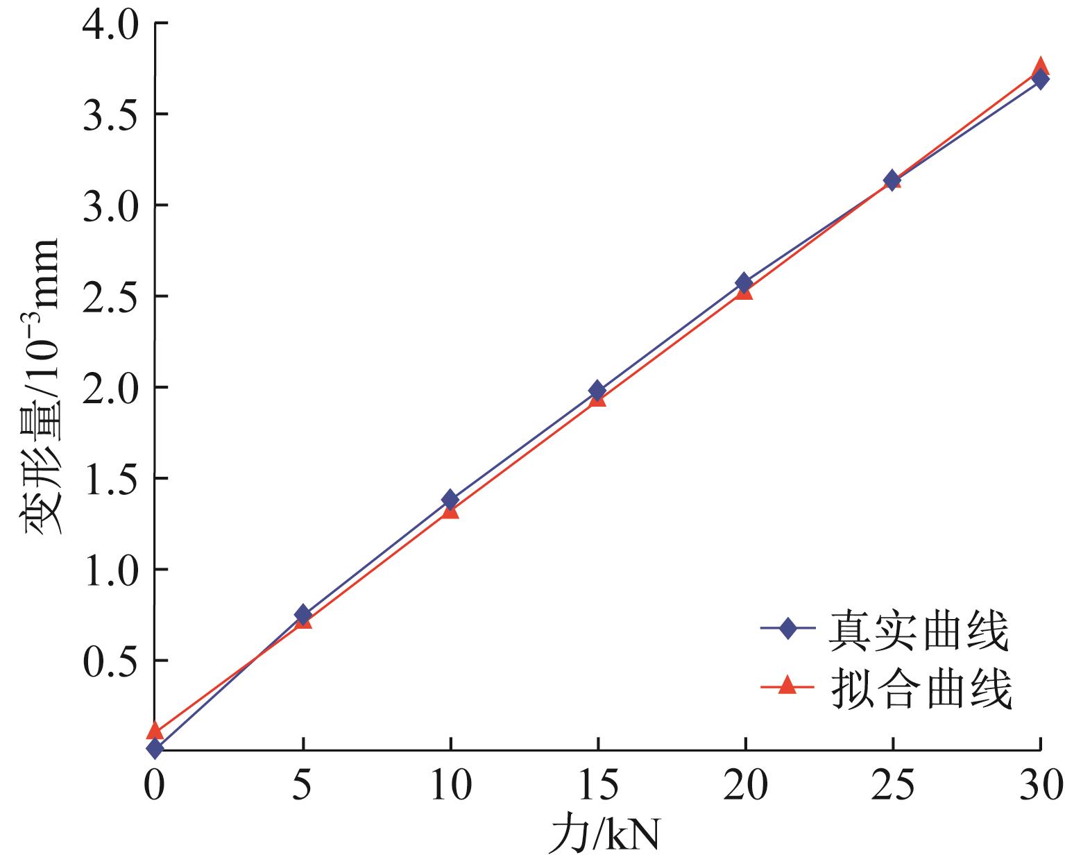
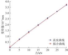
Fig.10 Comparison of contact stiffness curves of single roller
|
|
|
|
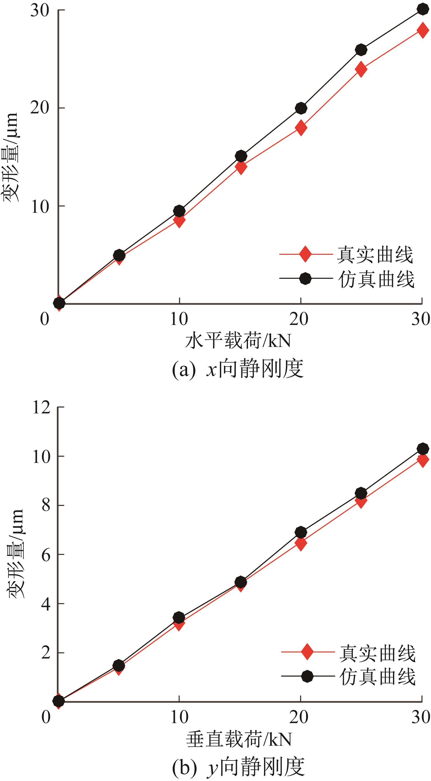
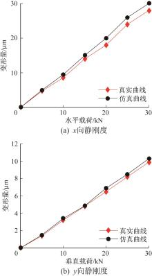
Fig.11 Comparison of static stiffness curves of slider
|
|
|
|
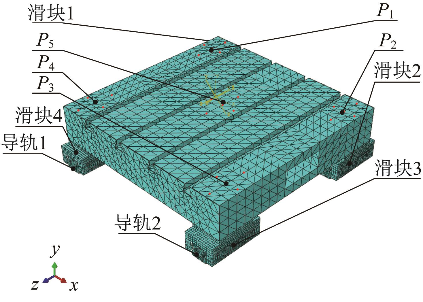
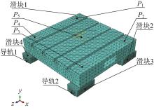
Fig.12 Finite element model of linear feed system with double guide rails and four sliders
|
|

|
|
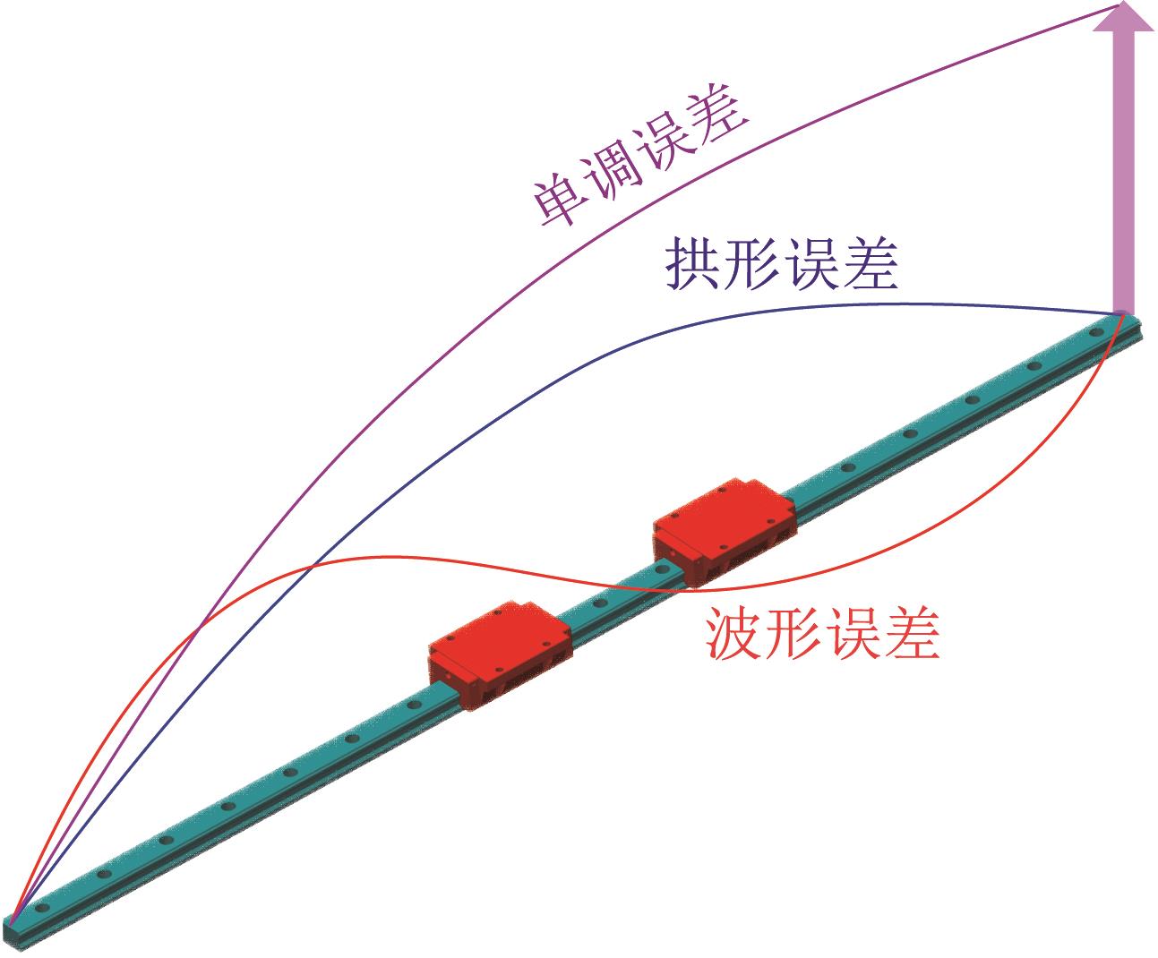
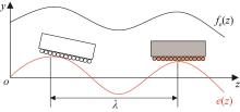
Fig.13 Schematic diagram of geometric error form of guide rail
|
|
|
|
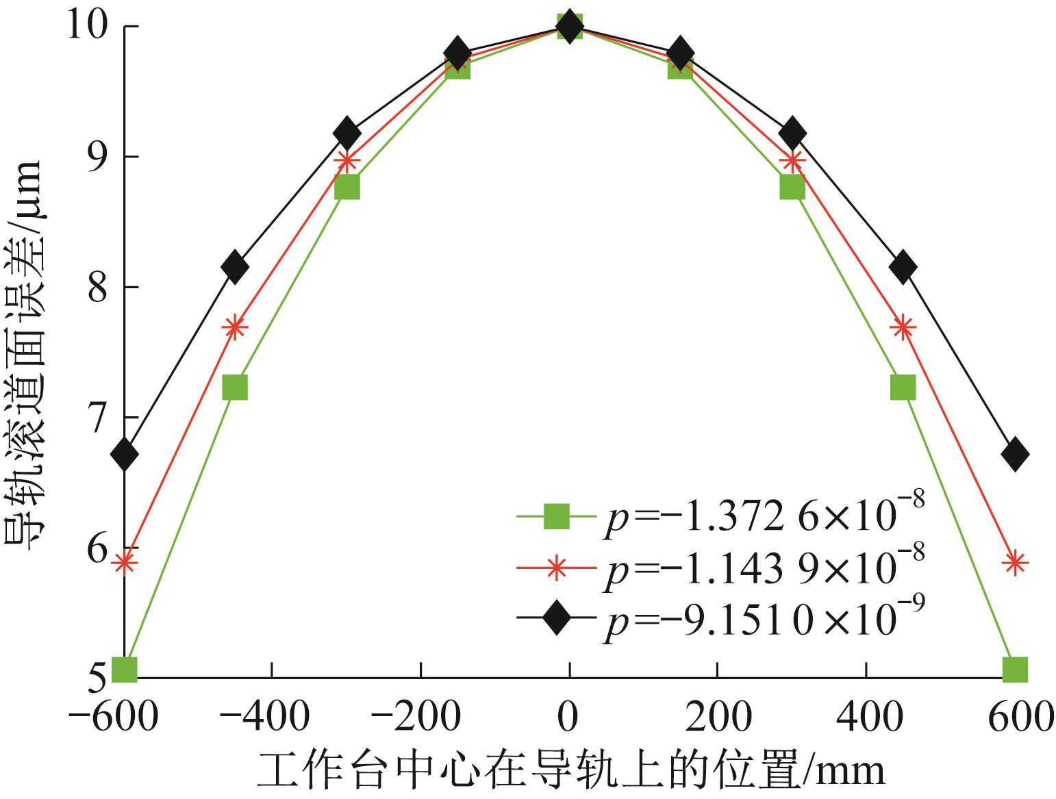
Fig.14 Geometric error forms of guide rail corresponding to different coefficients p
|
|
|
|
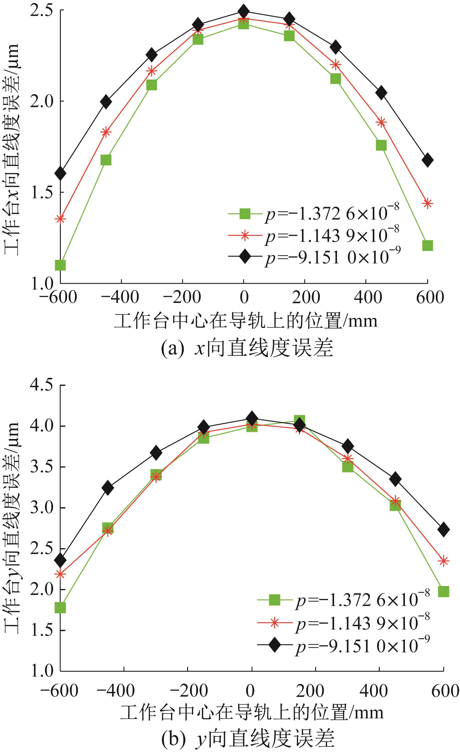
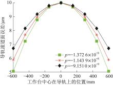
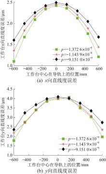
Fig.15 Influence of coefficient p on straightness error of workbench
|
|
|
|
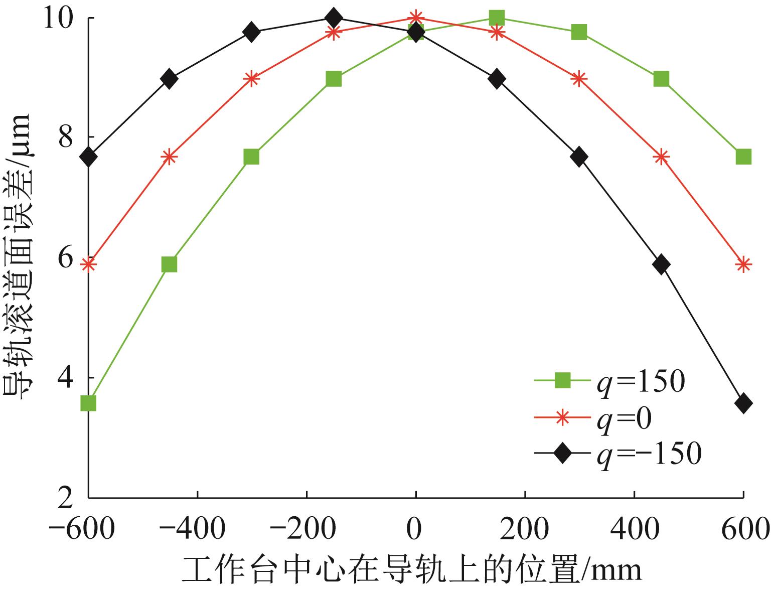
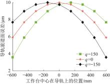
Fig.16 Geometric error forms of guide rail corresponding to different coefficients q
|
|
|
|
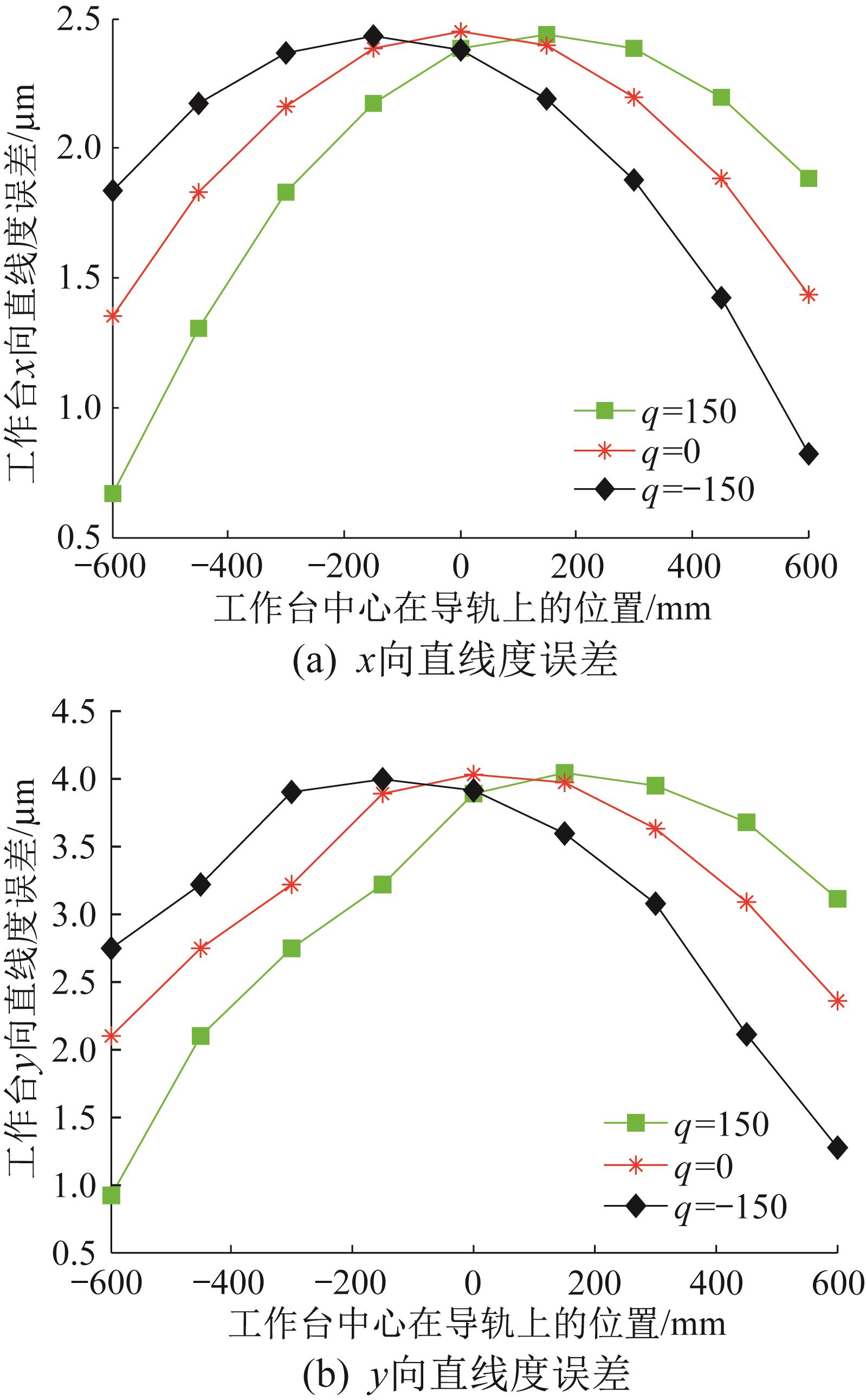
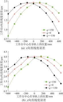
Fig.17 Influence of coefficient q on straightness error of workbench
|
|
|
|
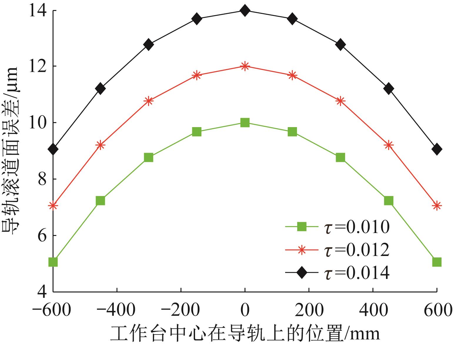
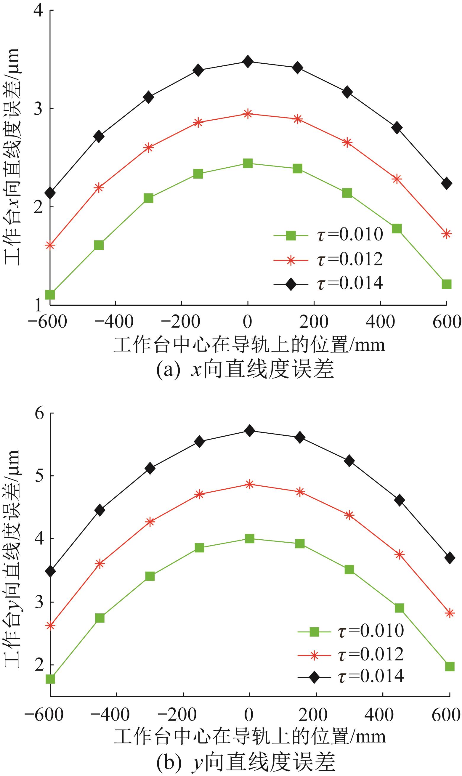
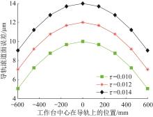
Fig.18 Geometric error forms of guide rail corresponding to different coefficients τ
|
|

|
|
Fig.19 Influence of coefficient τ on straightness error of workbench
|
|
| 参数 | 数值 |
|---|
| 床身 | 1 800×600×485 | | 工作台 | 570×550×102 | | 导轨跨距 | 474 | | 滑块间距 | 443 |
|
|
Table 2 Parameters of experimental platform for error averaging mechanism analysis
|
|
| 仪器及工具 | 用途 | 备注 |
|---|
| 光电准直仪 | 用于测量导轨安装基面、滑块面和工作台的直线度误差 | AIM系列,分辨率为0.01,精度为0.1 | | 扭矩扳手 | 对导轨的固定螺栓施加规定的拧紧力矩 | 力矩为5~60 Nm | | 水平仪 | 平行度测量和角度调整 | 0.02 mm/m |
|
|
Table 3 Instruments and tools used in error averaging mechanism analysis experiment
|
|

|
|
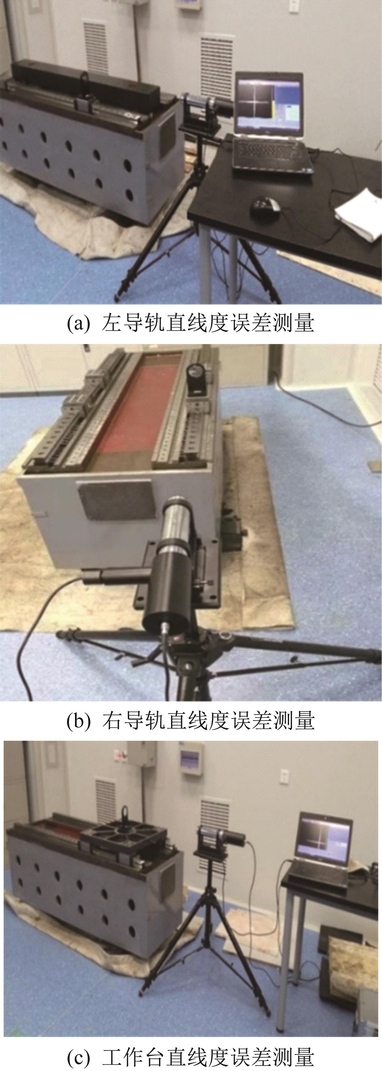
Fig.20 Measurement site of straightness error of guide rail and workbench
|
|

|
|
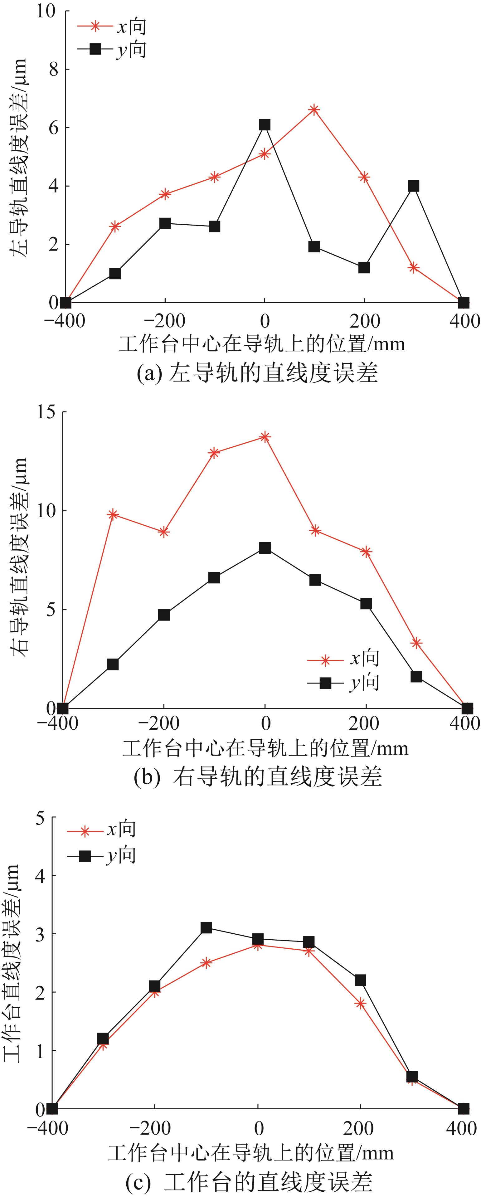
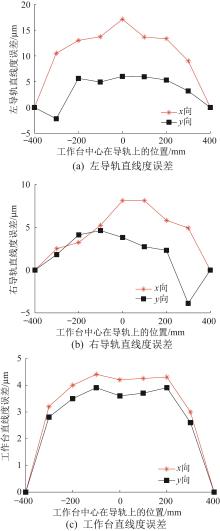
Fig.21 Measurement results of straightness error of guide rail and workbench (1st experiment)
|
|
| 部件 | 直线度误差 |
|---|
| x向 | y向 |
|---|
| 左导轨 | 6.600 | 6.100 | | 右导轨 | 13.700 | 8.100 | | 导轨副 | 10.150 | 7.100 | | 工作台 | 2.820 | 3.070 |
|
|
Table 4 Error transmission of linear feed system in the first experiment
|
|
| 比较项 | 直线度误差均化系数 |
|---|
| x向 | y向 |
|---|
| 相对误差/% | 6.9 | 5.4 | | 仿真值 | 0.260 | 0.410 | | 实验值 | 0.278 | 0.432 |
|
|
Table 5 Comparison of experimental and simulation results of straightness error averaging coefficient (1st experiment)
|
|
|
|
Fig.22 Measurement results of straightness error of guide rail and workbench (2nd experiment)
|
|
| 部件 | 直线度误差 |
|---|
| x向 | y向 |
|---|
| 左导轨 | 19.470 | 8.050 | | 右导轨 | 9.530 | 8.220 | | 导轨副 | 14.500 | 8.135 | | 工作台 | 4.830 | 4.160 |
|
|
Table 6 Error transmission of linear feed system in the second experiment
|
|
| 比较项 | 直线度误差均化系数 |
|---|
| x向 | y向 |
|---|
| 相对误差/% | 28.1 | 24.6 | | 仿真值 | 0.260 | 0.410 | | 实验值 | 0.333 | 0.511 |
|
|
Table 7 Comparison of experimental and simulation results of straightness error averaging coefficient (2nd experiment)
|