

太阳能烟囱通风一般采用高位排风. 实际应用中,风压的影响不可忽略[11],风压既可能加强也可能会削弱热压产生的通风效果,甚至产生倒灌现象(空气由太阳能烟囱出口流向进口)[12]. 针对风压如何影响太阳能烟囱建筑热压通风的研究较少,现有研究大多集中于外部环境风的风速、风向方面. 比如,Hosien等[13]通过建立数学模型,考虑了入射太阳辐射,风速,环境温度,太阳能烟囱的高度、间距和宽度等参数对通风性能的影响. Neves等[14]利用Energy Plus和风洞实验,研究风干扰对太阳能烟囱性能的影响. 该研究的结论是风速对风量影响较大,质量流量随着风速的增加而增加;即使在低环境风速下(如0.6 m/s),当出口遇到迎风时,烟囱的体积流量将显著降低. Shi[15]对太阳烟囱与风的相互作用进行数值和理论研究,发现风速高并不代表太阳烟囱的性能一定好,影响太阳能烟囱性能的还有风向角α,即风向与带窗墙的外法线之间的角度,α = 0°为最佳风向角. 在真实风环境中,大气边界层的流动特性使得风在不同高度呈梯度分布,不仅进出口的相对方位,而且其相对高度都对烟囱的风压通风有重要影响. 因此太阳能烟囱建筑出口设计,须考虑梯度风下风压. 必须指出,烟囱出口与捕风器的应用功能不同,后者是风压通风的入口,利用高处的环境风产生的正压通过风口和风道将风最大限度地引入建筑内部,再通过窗户或其他开口排出室外 [16-18]. 此外,为了消除或降低风压的影响,出口可以设置风帽[19],但有关风帽的实际效果的数据较少.
针对上述问题,搭建太阳能烟囱建筑的缩尺模型,通过风洞实验,研究在梯度风作用下,出口设置弯管、2种不同的风帽对太阳能烟囱建筑风压分布及通风量的影响.
1. 风洞实验
1.1. 实验方案
如图1所示,实验在浙江大学土木水利工程实验中心风洞试验平台中进行,风洞试验段长18.0 m,宽4.0 m,高3.0 m. 实验模型根据相似原理,采用缩尺模型,房间及烟囱模型按照1∶10的比例缩小,并使用厚3.0 mm的透明亚克力板制作尺寸为0.3 m×0.3 m×0.3 m的建筑模型. 实验中阻塞率为0.8%,低于现有文献建议的最大允许值3%[14,20]. 如图2所示,该模型由正方形的房间和位于房间背面的太阳能烟囱组成. 房间的正面和左侧面各预设1个可以开启的窗口. 2个入口尺寸均为0.10 m×0.04 m,烟囱通道尺寸与之相同. 烟囱配置3种出口:普通弯管出口和2个带挡风功能的风帽. 风帽模型也按1∶10的比例缩小,并且保持出风有效面积和烟囱通道截面积相当. 当使用弯管时,整体模型高度为0.46 m. 如图3所示,2种风帽分别为百叶型风帽和挡板型风帽. 模型放置在风洞内的转盘上,旋转转盘可以获得不同的风向角,本研究测试4个方向的风向角,分别为0°、90°、180°、270°.
图 1
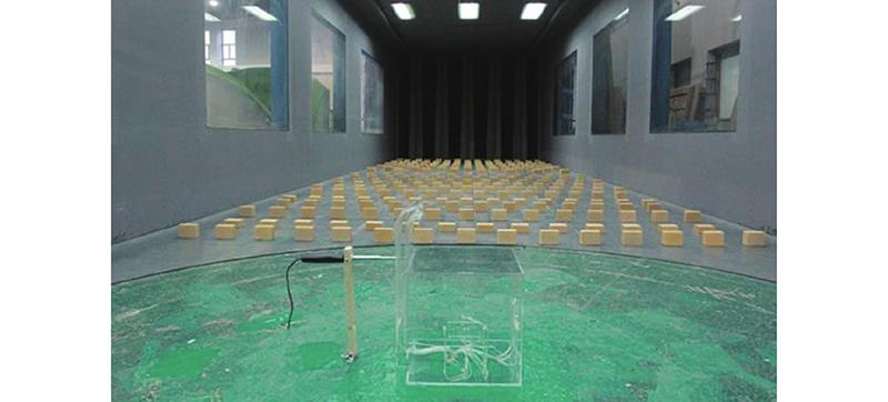
图 2
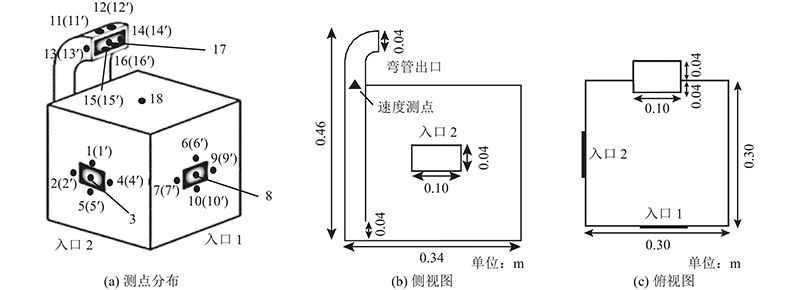
图 2 太阳能烟囱建筑模型及测点分布
Fig.2 Solar chimney building model and distributions of measuring points
图 3

风洞来流呈梯度分布,满足指数律风剖面关系式:
式中:Ur为参考高度
图 4

图 4 风洞实验中的5种风剖面 (参考高度为0.45 m)
Fig.4 Five wind profiles in wind tunnel test (reference height is 0.45 m)
1.2. 测点布置
实验使用风速计(TSI9545: 精度为±0.015 m/s)测量开口打开时太阳能烟囱通道内的风速. 使用电子压力扫描阀系统(范围为0~±25 Pa,精度为±0.15%)测量和记录建筑模型的内、外表面压强,频率为166 Hz. 实验主要测量各表面的中心点和进出口中心的压强,为了掌握出入口周围的压强分布,在出入口四周布置测点共32个. 测点位置布置见图2(a)、图3,其中有2个测点未在图2中标示,分别为背面中心点19(正对入口1)和右侧面中心点20(正对入口2). 大部分测点均同时测量内外表面压力,纯数字标号表示外压测点序号,带“’” 数字标号表示内压测点序号. 对于开口中心的测点(3、8、17),当开口封闭时,测量的是外表面压强;当开口打开时,测量的是来流的总压(即皮托管管口截面平行于出口平面).
1.3. 风压系数
考虑到大气边界层的流动特性,用梯度风模拟现实中的来流, 湍流的风廓线在模型表面的不同高度产生不同的压强. 开口关闭时测得的压强结果如表1所示. 表中,pin、pout分别为入口处、出口处测得的压强,Δp为进出口位置间的风压差. 无量纲量风压系数
表 1 进出口中心位置处的风压比较(参考风速为5 m/s)
Tab.1
| 工况 | 开口封闭 | 开口打开 | |||||
| | | Δp | | | Δp | ||
| Pa | |||||||
| 1 | 9.518 | 12.766 | −3.248 | 10.499 | 15.023 | −4.525 | |
| 2 | −5.749 | −10.434 | 4.685 | −6.551 | −7.928 | 1.377 | |
| 3 | −1.398 | −10.026 | 8.628 | −0.776 | −7.297 | 6.521 | |
| 4 | −5.504 | 12.766 | −18.270 | −5.062 | 16.254 | −21.316 | |
| 5 | −1.509 | −10.434 | 8.925 | −1.606 | −6.238 | 4.633 | |
| 6 | −6.213 | −10.026 | 3.814 | −5.272 | −7.677 | 2.405 | |
| 7 | 9.212 | −6.163 | 15.375 | 9.309 | −6.511 | 15.821 | |
式中:
2. 结果与分析
2.1. 风压系数分布
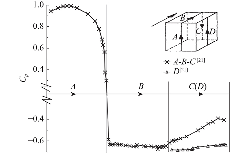
如图5所示为当开口均为封闭、
图 5

图 5 梯度风作用下2种模型的表面风压系数比较
Fig.5 Comparison of surface pressure coefficients between two models under gradient wind
图 6
2.2. 弯管出口实验结果
2.2.1. 进出口风压差
图 7

图 7 房间进出口布置以及4个风向角
Fig.7 Layout of room inlet and outlet and four tested wind directions
当开口封闭时,在梯度风作用下,模型迎风面风压为正,且位置较高的出口处风压大于低位置的入口处风压;侧面与背风面均出现负压,且位置较高的出口处风压小于位置较低点处的风压. 对于同一高度,位于背风面的负压比侧面的负压更大(工况5和工况6比). 表1中,当进出口压差Δp为负时(工况1和工况4)意味着出现倒流,即空气从太阳能烟囱流向房间,流动方向与热压设计方向相反. 在实际中,这会抵消部分或全部热压的影响[22]. 工况4出现倒灌,原因是出口在迎风面正压区,而入口在侧面的负压区. 工况1中,虽然进出口都在迎风面正压区,但是在梯度风下,更高的出口面风压大于处于低处的入口面,因此烟囱内产生倒流. 太阳能烟囱出口一般位于高处,因此在实际设计过程中,须在出口采取措施以避免烟囱内产生倒流,比如使用风帽. 当开口打开时,表1中的出口压强实际为烟囱流动的静压,入口压强为烟囱流动的背压或全压. 但烟囱内流速(< 1 m/s)多小于外部环境风速,因此可以认为压强主要受外部风压的影响. 测量得到的进出口压差符号和大小与封闭时的一致,除工况7进出口压差变化不大外,其他工况开口后的进出口压差均比封闭状态的压差小.
2.2.2. 弯管出口的体积流量
当房间进出口打开时,7种工况下体积流量
图 8
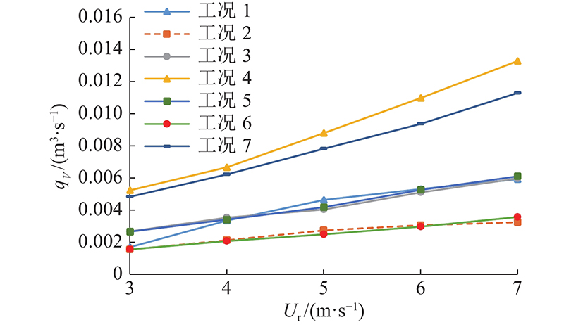
图 8 进出口不同方位布置下的体积流量
Fig.8 Volume flow rates under different layouts of inlet and outlet
2.3. 风帽出口实验结果
2.3.1. 进出口风压差
选取入口1作为房间入口,如表2所示为参考风速为5 m/s时弯管出口和2种风帽情况下的进出口处内侧压强. 表中,
表 2 不同出口形式的房间进出口处内侧压强(参考风速为5 m/s)
Tab.2
| 类型 | α/(°) | pin/Pa | | pout/Pa | | Δ | ||||||||
| 测点6′ | 测点7′ | 测点9′ | 测点10′ | 测点15′ | 测点16′ | 测点13′ | 测点14′ | 测点11′ | 测点12′ | |||||
| 百叶型风帽 | 0 | 7.872 | 8.132 | 7.898 | 7.740 | 7.910 | 5.249 | 5.032 | 5.025 | 5.066 | 4.972 | 5.085 | 5.071 | 2.839 |
| 90 | −5.635 | −5.604 | −5.612 | −5.426 | −5.569 | −7.092 | −7.282 | −7.145 | −6.709 | −7.533 | −7.129 | −7.148 | 1.579 | |
| 180 | −1.852 | −1.571 | −1.744 | −1.512 | −1.669 | −2.887 | −2.938 | −2.918 | −3.074 | −2.934 | −2.868 | −2.936 | 1.267 | |
| 挡板型风帽 | 0 | 5.359 | 5.365 | 5.304 | 5.393 | 5.355 | −3.640 | −3.748 | −2.769 | −3.324 | −3.178 | −3.399 | −3.343 | 8.690 |
| 90 | −5.310 | −5.413 | −5.346 | −5.127 | −5.299 | −6.654 | −6.674 | −6.557 | −6.709 | −6.645 | −7.087 | −6.721 | 1.422 | |
| 180 | −2.990 | −2.959 | −3.090 | −2.676 | −2.928 | −8.296 | −8.250 | −7.899 | −8.187 | −8.080 | −8.400 | −8.185 | 5.257 | |
| 弯管出口 | 0 | 12.679 | 12.766 | 12.851 | 12.345 | 12.660 | 13.662 | 13.382 | 14.973 | 14.971 | 14.825 | 14.779 | 14.432 | −1.772 |
| 90 | −6.391 | −6.312 | −6.132 | −6.318 | −6.289 | −8.592 | −8.656 | −8.357 | −7.898 | −8.575 | −8.485 | −8.427 | 2.140 | |
| 180 | −3.951 | −3.890 | −3.725 | −3.738 | −3.826 | −7.738 | −7.836 | −7.951 | −7.996 | −7.624 | −7.716 | −7.810 | 3.984 | |
2.3.2. 风帽出口的体积流量
如图9所示为2种类型的风帽与弯管出口状态下的体积流量对比. 可以看出,所有测量情况下的体积流量仍然随着风速增加而增加. 对比安装不同类型出口时的房间流量,结合压强分布结果分析可以得到:1)对于百叶型风帽,所有方向上均未出现倒流,但
图 9
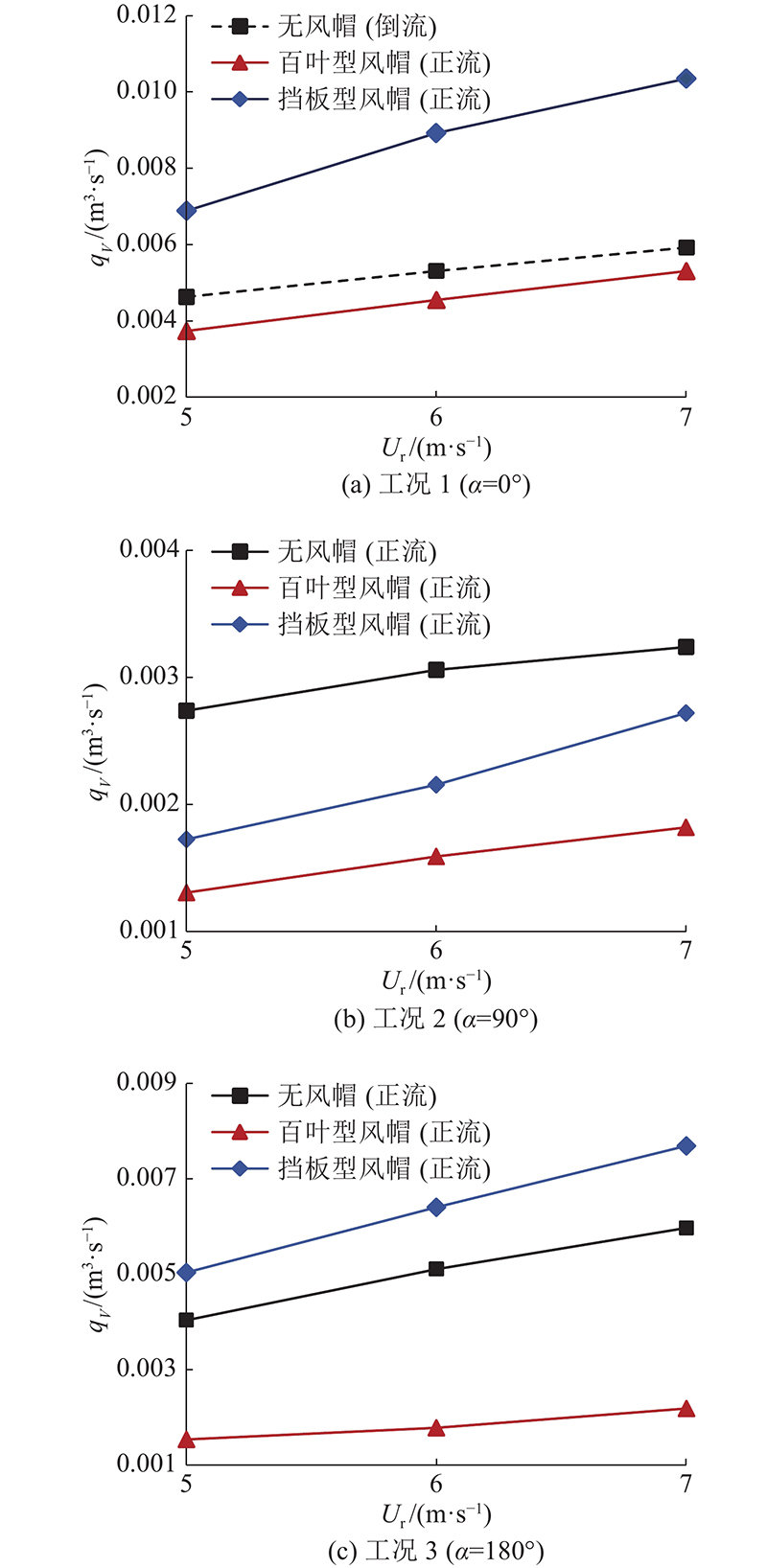
图 9 3种排风口下体积流量和参考风速的关系
Fig.9 Volume flow rates versus reference velocity at three exhausts
3. 结 论
(1)针对风压设计中进出口布置以及风帽对建筑高位排风的影响,设计了太阳能烟囱建筑缩尺模型,通过风洞试验,研究弯管出口和2种风帽(百叶型和挡板型)对烟囱通风的影响.
(2)在高位排风设计计算过程中,应考虑实际风环境中梯度风的作用. 在布置房间开口位置时,海拔越高,对应位置处的正压越大、负压越小. 太阳能烟囱出口处于高位,普通弯管出口在迎风时会出现与热压通风方向相反的倒流. 在设计中,应把烟囱出口设置在主流风向的背风面或侧面;房间进口优先布置在迎风面,原因是此时风压通风可以大大增强热压通风效果.
(3)出口使用风帽可以避免倒流现象,本研究结果表明,挡板型风帽的性能优于百叶型风帽的性能. 与弯管出口相比,百叶型风帽在风向角分别为0°、90°、180°时的风压通风体积流量分别减少15%、48%、63%;挡板型风帽在3个风向角上的体积流量分别为增大64%、减小28%、增加26%. 因此,在太阳能烟囱出口设计中推荐使用挡板型风帽.
(4)实际建筑自然通风是热压和风压综合作用的结果. 研究中有关风压通风的结论不受热压存在与否的影响. 如需同时考虑风压和热压,可以分别计算进出口处风压压差和热压压差,再进行叠加.
(5)研究结果证实了可以通过合适的风貌设计减少风压对热压通风的不利影响,但高处风压本身也是能源,通过诸如捕风塔技术可以直接用来进行建筑通风. 下一步计划结合捕风塔技术,研究在不减弱热压通风的情况下,最大限度利用风压通风.
参考文献
Annual energy performance simulation of solar chimney in a cold winter and hot summer climate
[J].DOI:10.1007/s12273-019-0572-y [本文引用: 2]
A CFD based approach for determining the optimum inclination angle of a roof-top solar chimney for building ventilation
[J].DOI:10.1016/j.solener.2020.01.017 [本文引用: 1]
多层建筑太阳能烟囱的全年通风潜力评价
[J].
Evaluation of the annual ventilation potential of solar chimneys for multi-story buildings
[J].
Study of natural ventilation of houses by a metallic solar wall under tropical climate
[J].DOI:10.1016/S0960-1481(98)00783-6 [本文引用: 1]
Solar chimney for enhanced stack ventilation
[J].DOI:10.1016/0360-1323(93)90042-2 [本文引用: 1]
An experimental investigation of a solar chimney model with uniform wall heat flux
[J].DOI:10.1016/S0360-1323(03)00057-X [本文引用: 1]
A new analytical model for airflow in solar chimneys based on thermal boundary layers
[J].DOI:10.1016/j.solener.2016.07.041 [本文引用: 1]
A general model for predicting the airflow rates of a vertically installed solar chimney with connecting ducts
[J].DOI:10.1016/j.enbuild.2020.110481 [本文引用: 1]
Ventilation performance of solar chimney in a test house: field measurement and validation of plume model
[J].DOI:10.1016/j.buildenv.2021.107648 [本文引用: 1]
Numerical study on mixed buoyancy-wind driving induced flow in a solar chimney for building ventilation
[J].DOI:10.1016/j.renene.2010.02.009 [本文引用: 1]
Experimental technique to determine unsteady flow in natural ventilation stacks at model scale
[J].
Effects of the geometrical and operational parameters and alternative outer cover materials on the performance of solar chimney used for natural ventilation
[J].DOI:10.1016/j.enbuild.2016.12.041 [本文引用: 1]
Simulation and measurements of wind interference on a solar chimney performance
[J].DOI:10.1016/j.jweia.2018.05.020 [本文引用: 2]
Impacts of wind on solar chimney performance in a building
[J].DOI:10.1016/j.energy.2019.07.056 [本文引用: 1]
Numerical simulation of cooling performance of wind tower (Baud-Geer) in hot and arid region
[J].
基于捕风器的建筑被动通风性能研究
[J].
Study on passive ventilation performance of buildings using wind catcher
[J].
风帽的合理设计可强化地下空间自然通风
[J].
The reasonable design of hood can strengthen the natural ventilation of underground space
[J].
The flow around a surface-mounted cube in uniform and turbulent streams
[J].DOI:10.1017/S0022112077000172 [本文引用: 5]
