|
|
|
| Measurement of movable wing surface deflection based on wireless inclination sensor |
Peiqi ZHANG1( ),Bofeng LIU2,Mingqi CUI1,Zheng HU2,Qing WANG1,*() ),Bofeng LIU2,Mingqi CUI1,Zheng HU2,Qing WANG1,*() |
1. Key Laboratory of Advanced Manufacturing Technology of Zhejiang Province, School of Mechanical Engineering, Zhejiang University, Hangzhou 310027, China
2. Xi’an Aircraft Industrial (Group) Co. Ltd, Xi’an 710089, China |
|
|
|
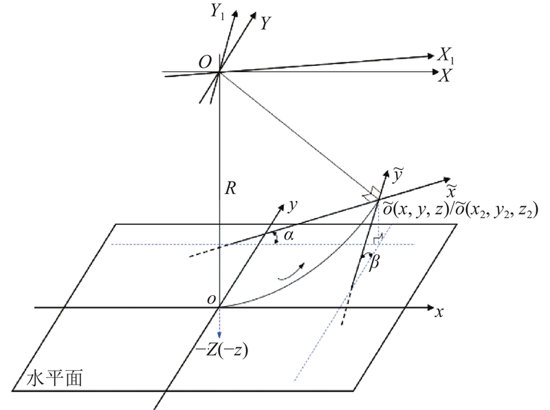
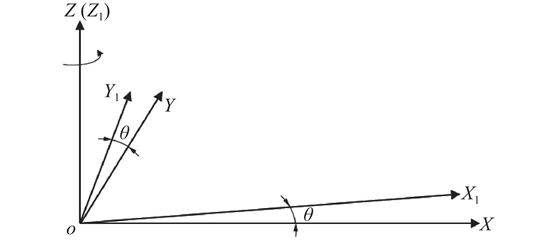
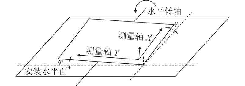
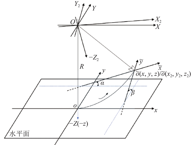
Abstract The dual measurement axis spatial rotation model was deduced and improved, by referring to the existing spatial angle measurement models and considering the system error of the aircraft testing site, based on the analysis of the underlying measurement principle of the inclination sensor. The purpose was to resolve the problems during the movable wing surface deflection test, such as high installation parallelism requirement, long cables and complex manual operations, so as to improve the measurement accuracy and the test efficiency. A spatial angle measurement error model around the horizontal axis and a calibration method for inclination sensor were proposed, to meet the requirement for the deflection testing. A large aircraft movable wing surface deflection testing system based on wireless inclination sensors was designed and implemented, capitalizing on this model and the calibration method. Results of the rotation angle accuracy testing on the experimental platform and the on-site testing on the movable wing surface show that, compared with the existing methods, the proposed calibration method can obtain a larger effective measurement range to meet the actual working conditions, improve the angle calibration accuracy, and significantly improve the testing efficiency.
|
|
Received: 30 March 2023
Published: 05 March 2024
|
|
|
| Fund: 国家重点研发计划资助项目(2019YFB1707504). |
|
Corresponding Authors:
Qing WANG
E-mail: 22125032@zju.edu.cn;wqing@zju.edu.cn
|
基于无线倾角传感器的活动翼面偏转测试
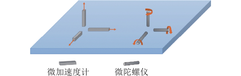
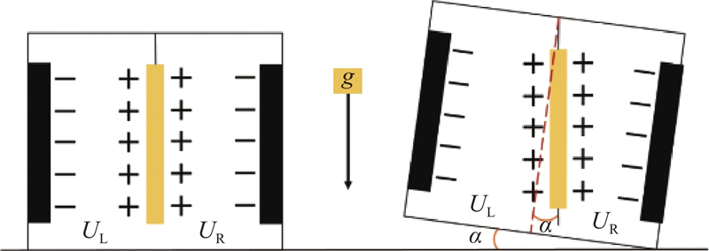
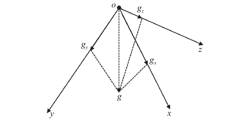
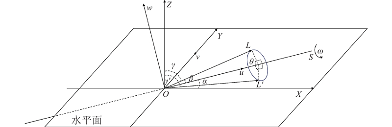
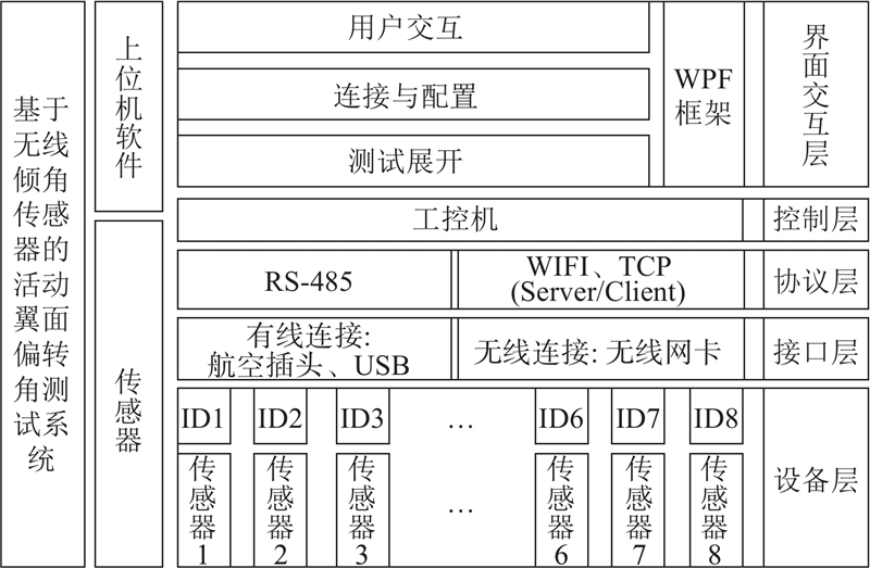
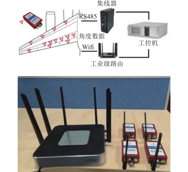
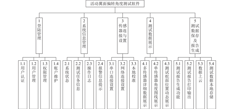
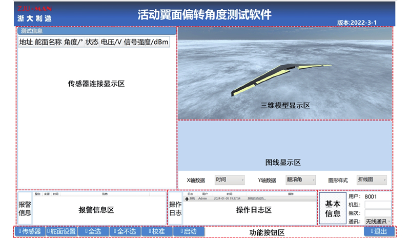
为了解决传统活动翼面偏转测试中传感器安装平行度要求高、线缆长、人工操作复杂繁琐等问题,提高空间角度测量准确性和现场测试效率,在分析倾角传感器底层测量原理的基础上,综合考虑飞机测试现场系统误差,参考已有的空间角度测量模型,对双测量轴空间旋转模型进行推导和改进. 得到适用于机翼活动翼面绕水平轴偏转情况下的空间角度测量误差模型,提出适用于活动翼面偏转测试需求的倾角传感器校准方法. 以该模型和校准方法为基础设计实现基于无线倾角传感器的大型飞机活动翼面偏转测试系统. 实验平台旋转角度精度测试和活动翼面现场测试的结果表明,相对于现有方法,该校准方法能够获得更大有效测量量程以满足实际工况需求,提升角度校准精度,并显著提升测试效率.
关键词:
活动翼面,
角度测量,
倾角传感器,
校准算法,
偏转测试
|
|
| [1] |
范玉青 波音787飞机总装配线及其特点[J]. 航空制造技术, 2011, (Suppl. 2): 38- 42
FAN Yuqing Boeing 787 final assembly line and its characteristics[J]. Aeronautical Manufacturing Technology, 2011, (Suppl. 2): 38- 42
|
|
|
| [2] |
曹建安, 徐海虹, 吴昊, 等 飞机总装站位式生产线的综合测试技术研究[J]. 测控技术, 2017, 36 (2): 15- 19
CAO Jianan, XU Haihong, WU Hao, et al Research on integrative testing of movable stations final assembly line of airplanes[J]. Measurement and Control Technology, 2017, 36 (2): 15- 19
|
|
|
| [3] |
宋利康, 郑堂介, 朱永国, 等 飞机脉动总装智能生产线构建技术[J]. 航空制造技术, 2018, (1): 28- 32
SONG Likang, ZHENG Tangjie, ZHU Yongguo, et al Construction technologies of intelligent pulse production line for aircraft final assembly[J]. Aeronautical Manufacturing Technology, 2018, (1): 28- 32
|
|
|
| [4] |
胡铮. 大型机翼活动翼面安装调试技术研究[D]. 哈尔滨: 哈尔滨工业大学, 2019.
HU Zheng. Study on installation and debugging technology of large wing moving surface [D]. Harbin: Harbin Institute of Technology, 2019.
|
|
|
| [5] |
XIAO W J, CHEN Z B, MA D X, et al Large-scale spatial angle measurement and the pointing error analysis[J]. Optoelectronics Letters, 2016, 12 (3): 229- 232
doi: 10.1007/s11801-016-6028-z
|
|
|
| [6] |
彭希锋, 陈爽, 李海星, 等 基于激光位移传感器的面角度测量技术研究[J]. 仪器仪表学报, 2017, 38 (11): 2735- 2743
PENG Xifeng, CHEN Shuang, LI Haixing, et al Study on the plane angle measurement technology based on laser displacement sensors[J]. Chinese Journal of Scientific Instrument, 2017, 38 (11): 2735- 2743
|
|
|
| [7] |
牟成铭, 叶丁绮, 罗川 基于双目视觉的飞机活动翼面偏角测量研究[J]. 测控技术, 2020, 39 (8): 123- 128
MOU Chengming, YE Dingqi, LUO Chuan Deflection angle measurement of aircraft rudder based on binocular vision[J]. Measurement and Control Technology, 2020, 39 (8): 123- 128
|
|
|
| [8] |
CUYPERS W, VAN Gestel N, VOET A, et al Optical measurement techniques for mobile and large-scale dimensional metrology[J]. Optics and Lasers in Engineering, 2009, 47 (3/4): 292- 300
|
|
|
| [9] |
叶声华, 邾继贵, 张滋黎, 等 大空间坐标尺寸测量研究的现状与发展[J]. 计量学报, 2008, 29 (Supp1.1): 1- 6
YE Shenghua, ZHU Jigui, ZHANG Zili, et al Status and development of large-scale coordinate measurement research[J]. Acta Metrologica Sinica, 2008, 29 (Supp1.1): 1- 6
|
|
|
| [10] |
佀明华, 王伟明, 张勇, 等 基于光电伺服平台的动态角度测量方法研究[J]. 光电工程, 2019, 46 (10): 12- 18
SI Minghua, WANG Weiming, ZAHNG Yong, et al Research on dynamic angle measurement method based on electro-optical servo platform[J]. Opto-Electronic Engineering, 2019, 46 (10): 12- 18
|
|
|
| [11] |
WU B, WANG B Automatic measurement in large-scale space with the laser theodolite and vision guiding technology[J]. Advances in Mechanical Engineering, 2013, (1): 533- 542
|
|
|
| [12] |
张应猛. 一种飞机活动翼面偏转角度测量装置: CN106767647A [P]. 2017−05−31.
|
|
|
| [13] |
郑博, 谢云, 后柏宇, 等. 一种飞机活动翼面偏转角度测量方法: CN112729221A [P]. 2021−04−30.
|
|
|
| [14] |
WANG S, WEI X, WENG Y, et al A novel single-axis mems tilt sensor with a high sensitivity in the measurement range from 0° to 360°[J]. Sensors, 2018, 18 (2): 346- 358
doi: 10.3390/s18020346
|
|
|
| [15] |
ZHU J X, WANG W F, HUANG S P, et al An improved calibration technique for mems accelerometer-based inclinometers[J]. Sensors, 2020, 20 (2): 452- 474
doi: 10.3390/s20020452
|
|
|
| [16] |
曹建安, 张乐平, 吴昊, 等 采用倾角传感器实现空间旋转角度测量的解析方法研究[J]. 西安交通大学学报, 2013, 47 (10): 109- 114
CAO Jianan, ZHANG Leping, WU Hao, et al Analytical approach for measurement of spatial angle with inclination sensor[J]. Journal of Xi’an Jiaotong University, 2013, 47 (10): 109- 114
doi: 10.7652/xjtuxb201310019
|
|
|
| [17] |
CUI S W, CUI L G, DU Y D, et al. Calibration of MEMS accelerometer using kaiser filter and the ellipsoid fitting method [C]// Proceedings of the 37th Chinese Control Conference . Wuhan: [s.n.], 2018: 1243−1248.
|
|
|
| [18] |
张起朋, 李醒飞, 谭文斌, 等. 双轴倾角传感器姿态角测量的建模与标定[J]. 机械科学与技术, 2016, 35(7): 1096−1101.
ZHANG Qipeng, LI Xingfei, TAN Wenbin, et al. Modeling and calibration of dual-axis tilt sensor for measuring attitude angles[J]. Mechanical Science and Technology for Aerospace Engineering . 2016, 35(7): 1096−1101.
|
|
|
|
Viewed |
|
|
|
Full text
|
|
|
|
|
Abstract
|
|
|
|
|
Cited |
|
|
|
|
| |
Shared |
|
|
|
|
| |
Discussed |
|
|
|
|