Torque test of the drive shaft is the main means to disassemble the resistance of the vehicle chassis (including tires) and analyze the energy flow. Aiming at the demand of quick test of vehicle drive shaft torque, a test system which could be applied to different vehicle types was developed. Firstly, the overall architecture of the drive shaft torque test system was designed, which included sensing assembly, wireless acquisition assembly and calibration bench, and key hardware was selected; secondly, a sensing component that could achieve wide temperature compensation and axial moment decoupling was designed using biaxial patch bridge technology, and a rechargeable shaft sleeve that could adapt to narrow spaces was developed, which was made by 3D printing technology, and could support testing endurance requirements of over 20 hours and meet the layout, power supply, and thermal radiation resistance requirements of sensing components; then, a fast calibration test bench suitable for large axial angle deformation of the driving shaft after loading was designed; finally, the developed torque test system was calibrated, and road test and drum test were conducted. The results showed that the linearity of the drive shaft torque calibration reached 99.811%, and the test system had good performance and high test accuracy. The designed vehicle drive shaft torque test system has the advantages of fast calibration and test, portability and reusability of key sensing modules, and has high practical application value.
Yu TANG,Liang TAO,Yi XU,Heng WANG,Bin CHEN,Xiaolong ZHANG. Development and test of vehicle drive shaft torque test system. Chinese Journal of Engineering Design, 2023, 30(6): 789-796.
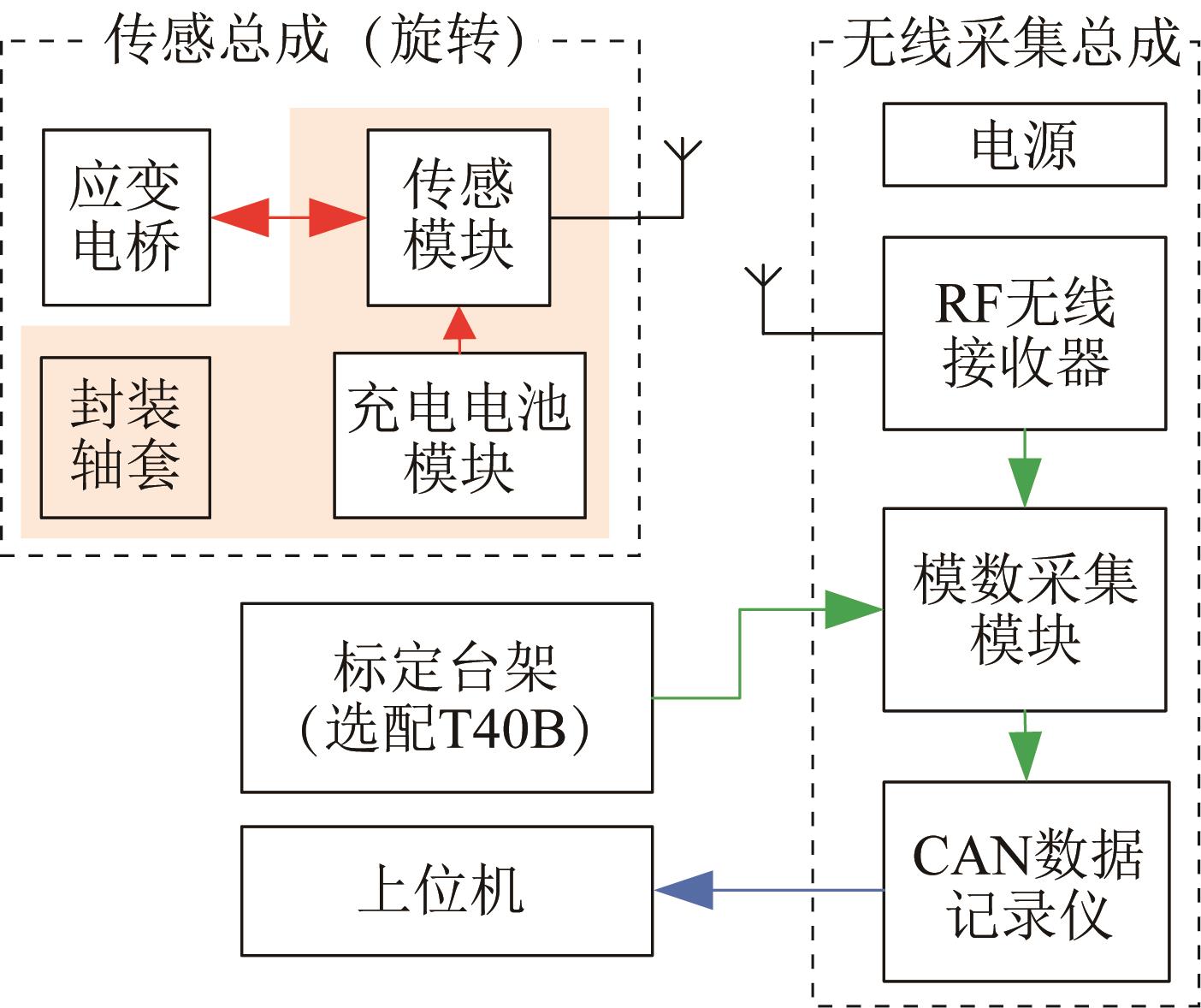
Fig.1 Structural block diagram of drive shaft torque test system
元件
厂地/型号
性能参数
供电形式
传感模块
德国/ datatel dt 1001T-ST
输出:±2 V,输入:±50 mV,阻值≥350 Ω
工作温度:-40~125 ℃
DC 5.1~9 V
RF无线接收器
德国/ datatel dt 1001R2-S
模拟输出:±10 V,工作温度:0~40 ℃
DC 10~32 V
模数采集模块
英国/ Influx
8路差分16位模数通道,精度:±0.001 5%
采样率:1 kHz
DC 4~36 V
应变片
日本/ KFGS-2-120-D31-11
硬化后工作温度:-196~120 ℃
自动补偿温度:10~100 ℃,电阻:350 Ω
线性膨胀系数:11×10-6/℃
Table 1Performance parameters of each component of drive shaft torque test system
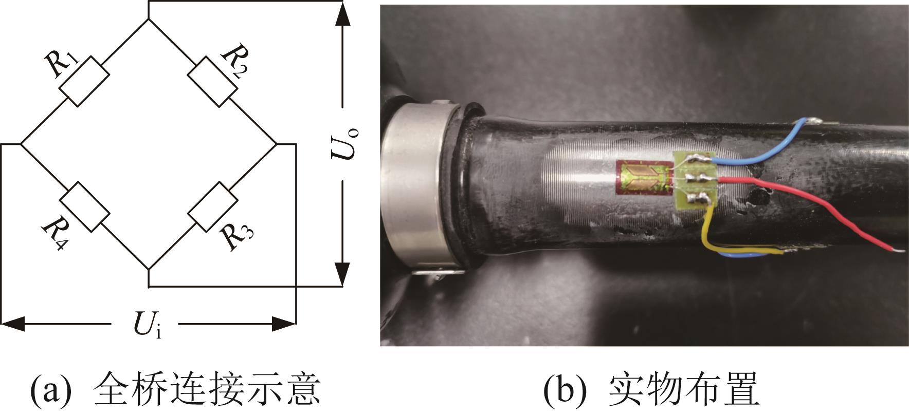
Fig.2 Full bridge connection schematic and physical arrangement of strain gauges
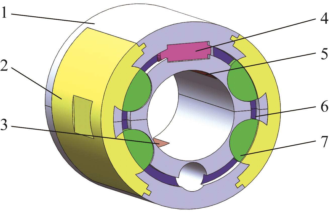
Fig.3 Schematic of shaft sleeve assembly
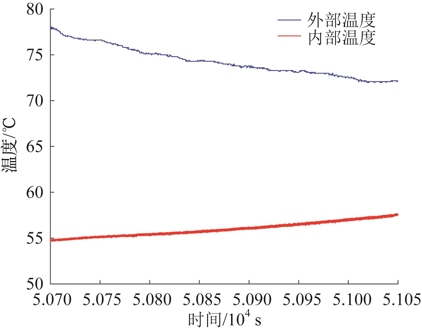
Fig.4 Comparison of internal and external temperature of shaft sleeve at speed of 10 km/h
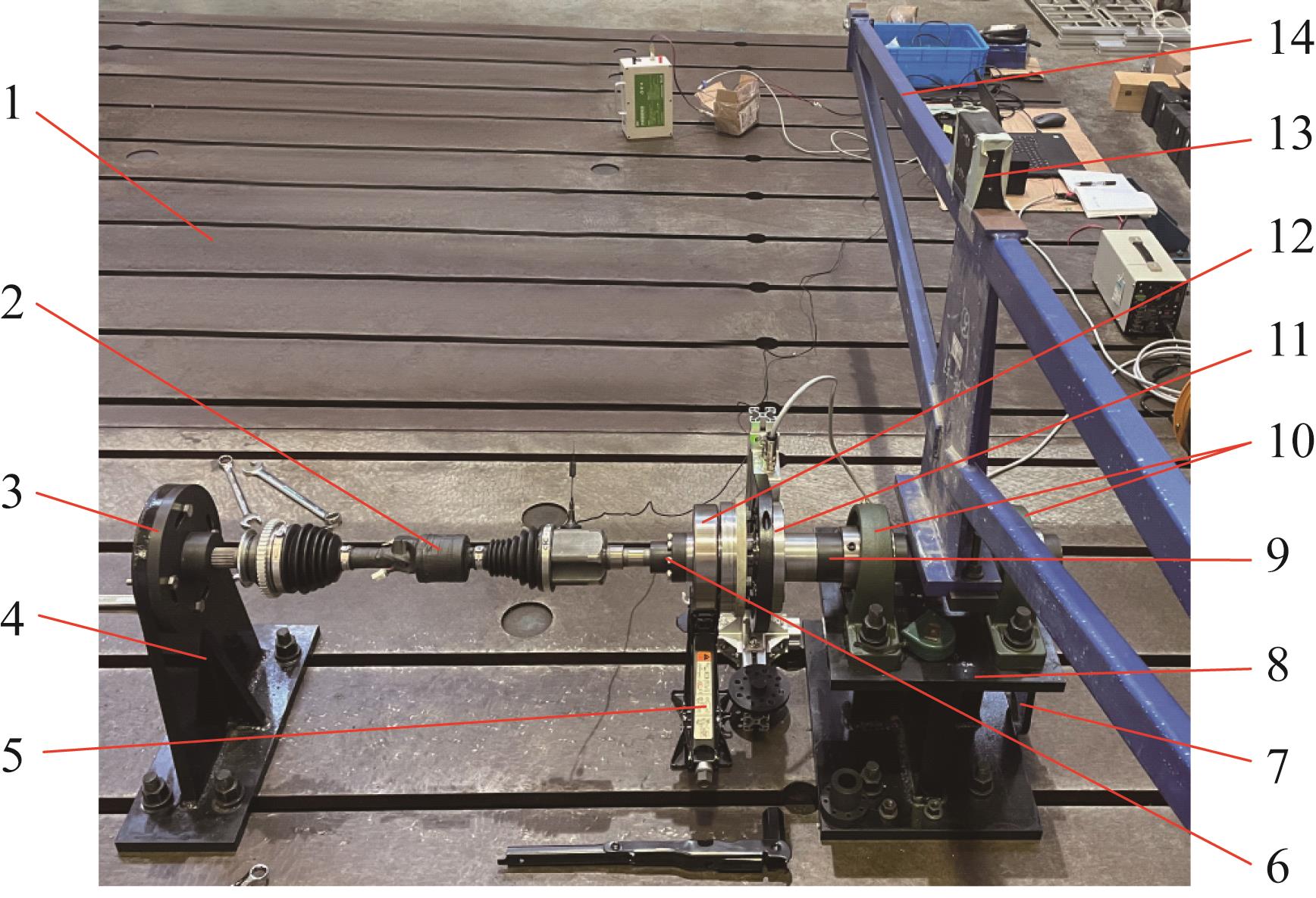
Fig.5 Calibration bench assembly
部件
材料
密度/
(kg/mm3)
弹性模量/Pa
泊松比
传力板
40 Cr
7.82×10⁻⁹
2.06×10¹¹
0.29
横臂
45号钢
7.85×10⁻⁹
2.06×10¹¹
0.27
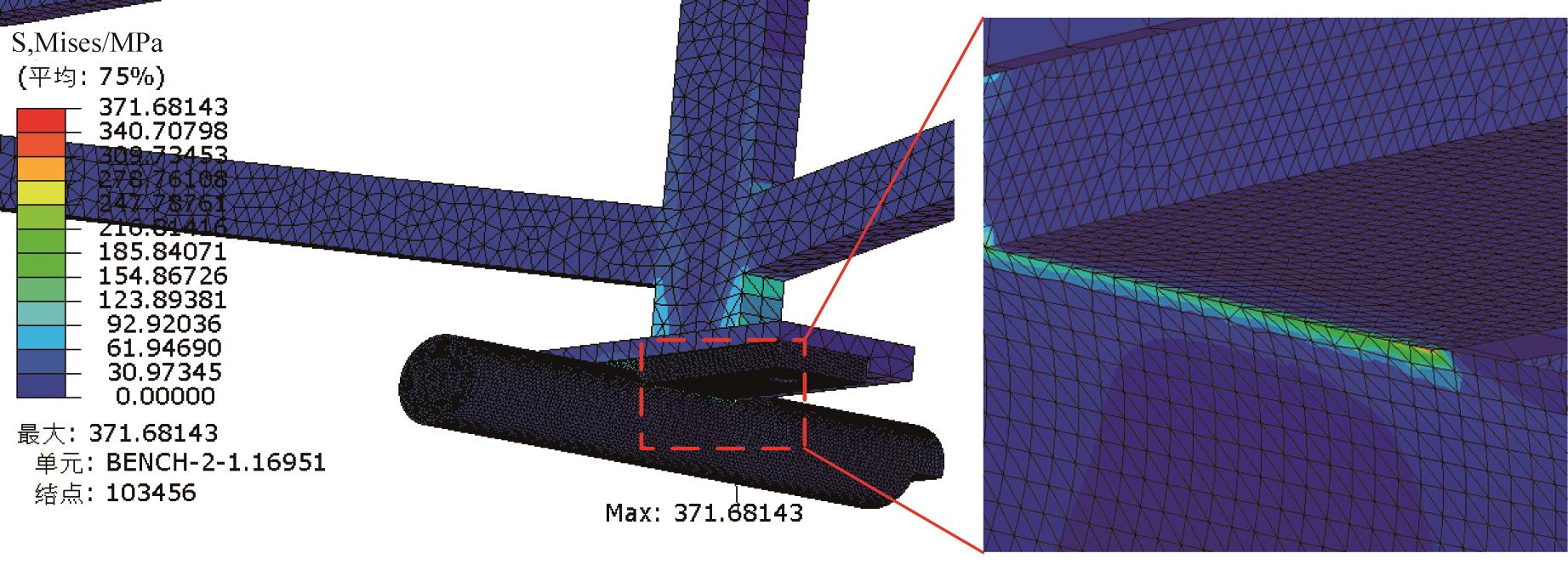
Table 2Material parameters of transmission plate and cross arm
Fig.6 Stress nephogram of assembly of transmission plate and cross arm
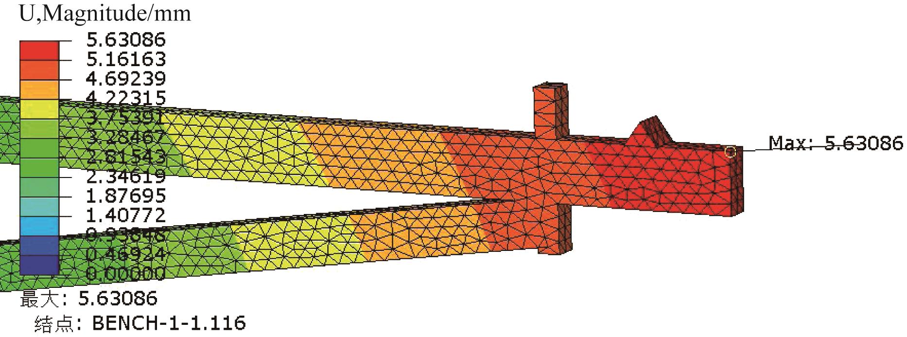
Fig.7 Displacement nephogram of assembly of transmission plate and cross arm
序号
砝码质量
m/ kg
传感总成输出
电压Us/ mV
T40B扭矩传感器
输出电压Ul / mV
1
28.0
1 355.12
-1 740.20
2
66.0
3 179.00
-4 080.15
3
34.0
1 642.29
-2 107.30
4
49.4
2 379.27
-3 056.29
5
36.5
1 762.22
-2 262.67
6
10.5
514.18
-660.16
7
15.0
-696.61
898.82
8
74.0
-3 515.96
4 486.43
9
53.5
-2 543.20
3 241.73
10
21.0
-1 001.11
1 263.44
11
9.0
-431.85
535.27
12
40.0
-1 903.68
2 421.85
13
29.4
-1 396.24
1 773.02
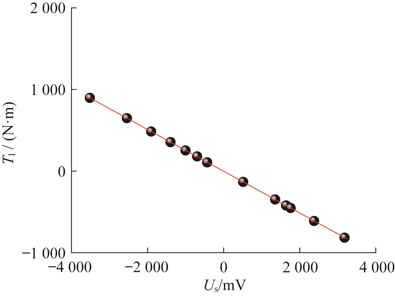
Table 3Data of calibration test of sensing assembly
Fig.8 Calibration curve of sensing assembly
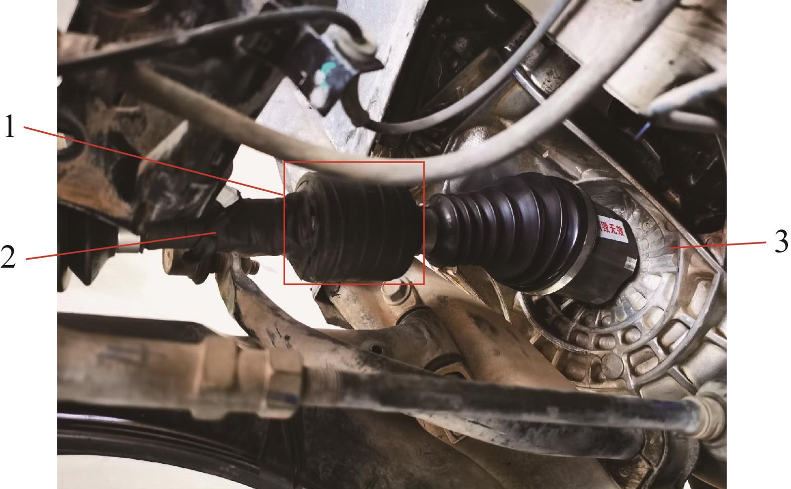
Fig.9 Installation diagram of sensing assembly
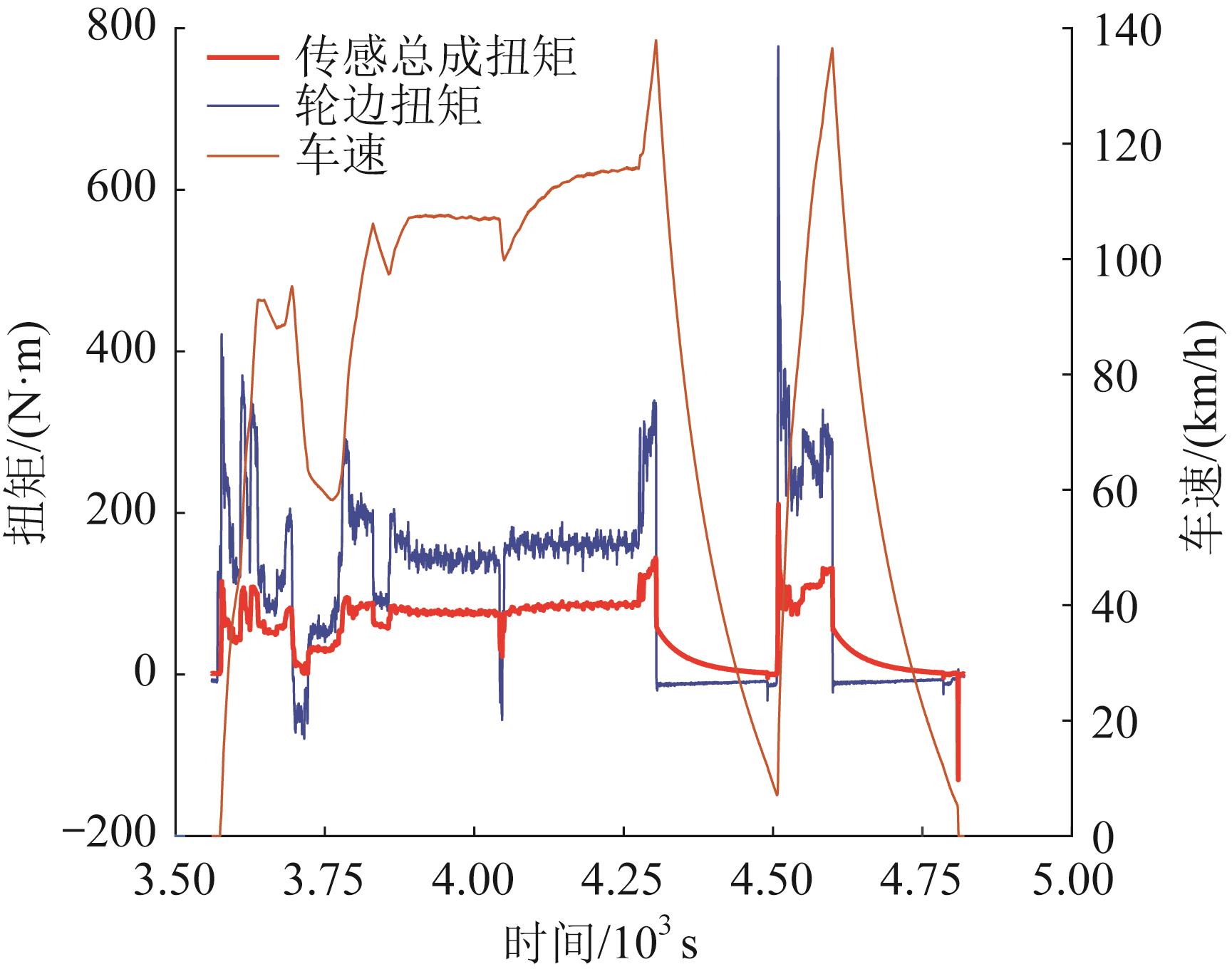
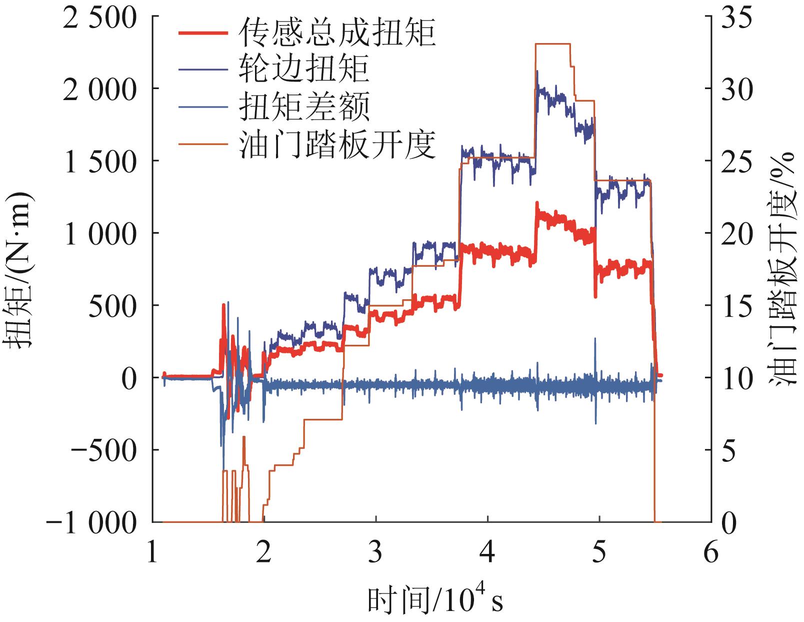
Fig.10 Test results of sensing assembly torque and wheel rim torque under variable vehicle speed
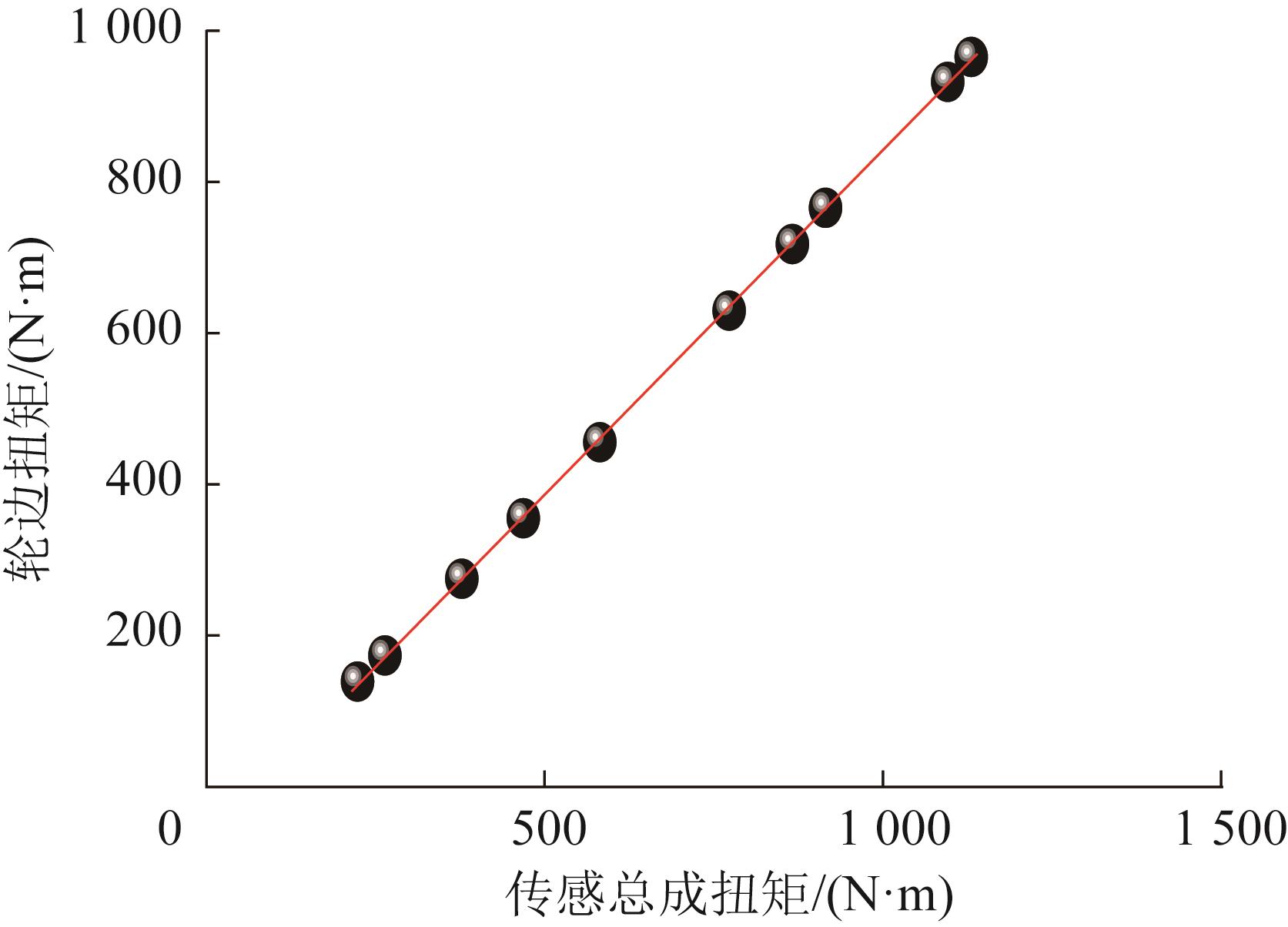
Fig.12 Relationship curve between sensing assembly torque and wheel rim torque under constant vehicle speed
[1]
杨翔宇,王刚,韩宗奇,等.基于能量流分析的汽车发动机与传动系匹配[J].汽车安全与节能学报,2015,6(1): 90-96. doi:10.3969/j.issn.1674-8484.2015.01.xx YANG X Y, WANG G, HAN Z Q, et al. Automobile engine and powertrain matching based on energy flow analysis[J]. Journal of Automobile Safety and Energy Conservation, 2015, 6(1): 90-96.
doi: 10.3969/j.issn.1674-8484.2015.01.xx
[2]
LIVSHIZ M, KAO M, WILL A. Validation and calibration process of powertrain model for engine torque control development[C]//SAE World Congress & Exhibition, Detroit,2004-03-08. doi:10.4271/2004-01-0902 .
doi: 10.4271/2004-01-0902
[3]
HU D S, HU Y F, CHEN H. Model-based calibration for torque control system of gasoline engine[C]//2014 International Conference on Mechatronics and Control (ICMC). Jinzhou, Jul. 3-5, 2014.
[4]
DE NOLA F, GIARDIELLO G, GIMELLI A, et al. Reduction of the experimental effort in engine calibration by using neural networks and 1D engine simulation[J]. Energy Procedia, 2018, 148: 344-351.
[5]
RAGHUNATH G, FLATAU A B. Wireless magneto-elastic torque sensor system[C]//52nd Aerospace Sciences Meeting, Maryland, Jan. 13-17, 2014.
[6]
PIETRON G M, FUJII Y, KUCHARSKI J, et al. Development of magneto-elastic torque sensor for automatic transmission applications[J]. SAE International Journal of Passenger Cars-Mechanical Systems, 2013(2): 529-534.
[7]
MULLER B. Characterizing the quasi-static and dynamic response of a non-contact magneto-elastic torque sensor[D]. Maryland: University of Maryland, College Park, 2017.
[8]
CHEN C X, MA T H, JIN H. Calibration method of capacitive grating torque sensor based on phase difference[J]. Electrotehnica, Electronica, Automatica, 2014, 62(4): 79.
[9]
MUFTAH M H, HARIS S M, PETROCZKI K, et al. An improved strain gauge-based dynamic torque measurement method[J]. International Journal of Circuits, Systems and Signal Processing, 2013, 7(1): 66-73.
[10]
CHEN C X, MA T H, JIN H, et al. Torque and rotational speed sensor based on resistance and capacitive grating for rotational shaft of mechanical systems[J]. Mechanical Systems and Signal Processing, 2020, 142: 106737.
[11]
BHAJANTRI V S, BAJANTRI S C, SHINDOLKAR A M, et al. Design and analysis of composite drive shaft[J]. International Journal of Research in Engineering and Technology, 2014, 3(3): 738-745.
[12]
张振乾,彭程,孙意凡,等.联合收获机喂入量监测系统信号分析与处理[J].农业机械学报,2019,50():73-78. doi:10.6041/j.issn.1000-1298.2019.S0.012 ZHANG Z Q, PENG C, SUN Y F, et al. Signal analysis and processing of combine harvester feedrate monitoring system[J]. Transactions of the Chinese Society for Agricultural Machinery, 2019, 50(): 73-78.
doi: 10.6041/j.issn.1000-1298.2019.S0.012
[13]
张永祥,明廷锋,张帅.应变扭矩的测量不确定度分析[J].测试技术学报,2018,32(3):185-190. doi:10.3969/j.issn.1671-7449.2018.03.001 ZHANG Y X, MING T F, ZHANG S. Measurement uncertainty analysis of strain torque[J]. Journal of Testing Technology, 2018, 32(3): 185-190.
doi: 10.3969/j.issn.1671-7449.2018.03.001
[14]
赵永峰,王玉,赖富文,等.基于NFC的无源无线扭矩测量系统[J].传感技术学报,2021,34(7):989-994. doi:10.3969/j.issn.1004-1699.2021.07.022 ZHAO Y F, WANG Y, LAI F W, et al. Passive wireless torque measurement system based on NFC[J]. Journal of Sensor Technology, 2021, 34(7): 989-994.
doi: 10.3969/j.issn.1004-1699.2021.07.022
[15]
张振乾,孙意凡,刘仁杰,等.联合收获机喂入量监测系统设计与试验[J].农业机械学报,2019,50(6):85-92. doi:10.6041/j.issn.1000-1298.2019.06.009 ZHANG Z Q, SUN Y F, LIU R J, et al. Design and test of feed rate monitoring system for combine harvester[J]. Transactions of the Chinese Society for Agricultural Machinery, 2019, 50(6): 85-92.
doi: 10.6041/j.issn.1000-1298.2019.06.009
[16]
LIN C, SUN S X, YI J, et al. Accelerated adaptive super twisting sliding mode observer‐based drive shaft torque estimation for electric vehicle with automated manual transmission[J]. IET Intelligent Transport Systems, 2019, 13(1): 160-167.
[17]
滑广军,吴运新,唐宏宾,等.高温和冲击作用下结构负载测试方法研究及应用[J].中南大学学报(自然科学版),2011,42(7):1981-1985. HUA G J, WU Y X, TANG H B, et al. Research and application of structural load testing methods under high temperature and impact[J]. Journal of Central South University (Science and Technology), 2011, 42(7): 1981-1985.
[18]
唐钰,张小龙,王恒,等.一种汽车传动系扭矩测试结构标定装置:ZL202220873702.0[P].2022-07-19. TANG Y, ZHANG X L, WANG H, et al. A structural calibration device for torque testing of automotive powertrains: ZL202220873702.0[P]. 2022-07-19.
[19]
陶亮,张大山,张小龙,等.智能轮胎开发平台专用轮辋总成设计与试验[J].中国机械工程,2023,34(9):1111-1119. doi:10.3969/j.issn.1004-132X.2023.09.012 TAO L, ZHANG D S, ZHANG X L, et al. Design and testing of special rim assembly for smart tire development platform[J]. China Mechanical Engineering, 2023, 34(9): 1111-1119.
doi: 10.3969/j.issn.1004-132X.2023.09.012