en
×

分享给微信好友或者朋友圈

使用微信“扫一扫”功能。
参考文献 1
FAOUZIN E E, LEUNGH, KURIANA. Data fusion in intelligent transportation systems: progress and challenge-A survey[J]. Information Fusion, 2010, 12(1): 4-10. doi:10.1016/j.inffus.2010.06.001
参考文献 2
曾庆喜,冯玉朋,杜金枝,等.融合视觉的智能车组合导航技术分析[J].导航定位学报,2017,5(2):1-6. doi:10.3969/j.issn.2095-4999.2017.02.001
ZENGQing-xi, FENGYu-peng, DUJin-zhi, et al. Analysis on integrated navigation technology for intelligent vehicles by integrating vision[J]. Journal of Navigation and Positioning, 2017, 5(2): 1-6.
参考文献 3
石慧.基于多传感器融合的车辆导航系统研究与实现[D].北京:北京工业大学城市交通学院,2016:7-10.
SHIHui. The research and implementation of vehicle navigation system based on multi-sensor fusion[D]. Beijing: Beijing University of Technology, College of Metropolitan Transportation, 2016: 7-10.
参考文献 4
姜岩,赵熙俊,龚建伟,等.简单城市环境下地面无人驾驶系统的设计研究[J].机械工程学报,2012,48(20):106-115. doi:10.3901/JME.2012.20.103
JIANGYan, ZHAOXi-jun, GONGJian-wei, et al. System design of self-driving in simplified urban environments[J]. Journal of Mechanical Engineering, 2012, 48(20): 106-115.
参考文献 5
HILLELA B, LERNERR, DAN L, et al. Recent progress in road and lane detection: a survey[J]. Machine Vision & Applications, 2014, 25(3): 727-745. doi:10.1007/s00138-011-0404-2
参考文献 6
郭俊杰.无人驾驶车GPS自主导航系统设计与实现[D].西安:长安大学汽车学院,2014:2-17.
GUOJun-jie. GPS navigation system design and implementation for driverless smart vehicles[D]. Xi’an: Chang’an University, School of Automobile, 2014: 2-17.
参考文献 7
WANGY, TEOHE K, SHEND. Lane detection and tracking using B-Snake[J]. Image & Vision Computing, 2003, 22(4): 269-280. doi:10.1016/j.imavis.2003.10.003
参考文献 8
叶美松.单目视觉的智能电动小车车道线识别与跟踪[D].成都:西南交通大学机械工程学院,2017:2-15.
YEMei-song. Lane recognition and tracking of intelligent electric vehicle based on monocular vision[D]. Chengdu: Southwest Jiaotong University, School of Mechanical Engineering, 2017: 2-15.
参考文献 9
JUNGC R, KELBERC R. Lane following and lane departure using a linear-parabolic model[J]. Image & Vision Computing, 2005, 23(13): 1192-1202. doi :10.1016/j.imavis.2005.07.018
参考文献 10
王海,蔡英凤,林国余,等.基于方向可变Haar特征和双曲线模型的车道线检测方法[J].交通运输工程学报,2014,14(5):119-126. doi:10.3969/j.issn.1671-1637.2014.05.015
WANGHai, CAIYing-feng, LINGuo-yu, et al. Lane line detection method based on orientation variance Haar feature and hyperbolic model[J]. Journal of Traffic and Transportation Engineering, 2014, 14(5): 119-126.
参考文献 11
鲁曼,蔡自兴,李仪.道路区域分割的车道线检测方法[J].智能系统学报,2010,5(6):505-509. doi:10.3969/j.issn.1673-4785.2010.06.007
LUMan, CAIZi-xing, LIYi. A lane detection method based on road segmentation[J]. CAAI Transactions on Intelligent Systems, 2010, 5(6): 505-509.
参考文献 12
KAEHLERA, BRADSKIG. Learning OpenCV 3: computer vision in C++ with the OpenCV library[M]. Sebastopol: O’Reilly Media Inc, 2016: 29-113.
参考文献 13
刘洪涛,蒋如意,胡文,等.基于路面垂直轮廓建模的一般路面逆透视变换[J].上海交通大学学报,2012,46(11):1770-1773.
LIUHong-tao, JIANGRu-yi, HUWen, et al. Inverse perspective mapping of general road based on vertical road profile modeling[J]. Journal of Shanghai Jiaotong University, 2012, 46(11): 1770-1773.
参考文献 14
SUNQian, ZHANGYa, WANGJian-guo, et al. An improved fast feature extraction based on RANSAC method of vision/SINS integrated navigation system in GNSS-denied environments[J]. Advances in Space Research, 2017, 60(12): 2660-2671. doi:10.1016/j.asr.2017.05.017
参考文献 15
侯长征.基于视觉的车道线检测技术研究[D].成都:西南交通大学信息科学与技术学院,2017:29-35.
HOUChang-zheng. Research on vision-based lane markings detection technology[D]. Chengdu: Southwest Jiaotong University, School of Information Science and Technology, 2017: 29-35.
参考文献 16
曹立波,陈峥,颜凌波,等.基于RFID、视觉和UWB的车辆定位系统[J].汽车工程,2017,39(2):225-231. doi:CNKI:SUN:QCGC.0.2017-02-017
CAOLi-bo, CHENZheng, YANLing-bo, et al. Vehicle positioning system based on RFID, Vision and UWB[J]. Automotive Engineering, 2017, 39(2): 225-231.
参考文献 17
段建民,石慧,刘丹,等.无人驾驶智能车导航系统控制研究[J].计算机仿真,2016,33(2):198-203. doi:10.3969/j.issn.1006-9348.2016.02.042
DUANJian-min, SHIHui, LIUDan, et al. Research of navigation control system for unmanned intelligent vehicles[J]. Computer Simulation, 2016, 33(2): 198-203.
参考文献 18
赵翔,杨明,王春香,等.基于视觉和毫米波雷达的车道级定位方法[J].上海交通大学学报,2018,52(1):33-38. doi:10.16183/j.cnki.jsjtu.2018.01.006
ZHAOXiang, YANGMing, WANGChun-xiang, et al. A lane-level positioning method based on vision and millimeter wave radar[J]. Journal of Shanghai Jiaotong University, 2018, 52(1): 33-38.
参考文献 19
李龙.基于OSM的移动GIS系统的研究与实现[D].北京:北京邮电大学自动化学院,2016:6-8.
LILong. Research and implementation of the mobile GIS system based on OSM[D]. Beijing: Beijing University of Posts and Telecommunications, School of Automation, 2016: 6-8.
参考文献 20
王晨学,平雪良,徐超.基于视觉辅助定位的机械臂运动学参数辨识研究[J].工程设计学报,2018,25(1):27-34. doi:10.3785/j.issn.1006-754X.2018.01.004
WANGChen-xue, PINGXue-liang, XUChao. Research on the kinematic parameter identification of robot arm based on the assistant location by stereo vision[J]. Chinese Journal of Engineering Design, 2018, 25(1): 27-34.
目录 contents

    摘要

    车辆定位导航系统实时、准确获取车辆位置对实现智能驾驶具有重要意义。针对传统定位导航系统存在的精度低、成本高、鲁棒性差等问题,基于GPS/INS(global positioning system /inertial navigation system,全球定位系统/惯性导航系统)、机器视觉和超声波雷达技术,设计了一种多传感器融合的智能车定位导航系统,旨在实现智能车在简单、结构化道路环境下的自动驾驶。利用GPS/INS技术实现智能车地理坐标获取,利用机器视觉技术实现智能车前方车道线检测,利用超声波雷达技术实现道路边沿检测,并对地理坐标、车道线和道路边沿数据进行深度融合,实现车道级定位导航。最后,进行了智能车定位导航现场测试,结果表明该系统满足车道级定位导航性能要求。研究结果表明,在简单、结构化道路环境下,多传感器融合的智能车定位导航系统结构简单,实际运行状况良好,可极大提高定位导航精度。

    Abstract

    In vehicle positioning and navigation system, real-time and accuracy of positioning are key indexes for intelligent driving. However, there are many problems in traditional positioning and navigation system, such as poor accuracy, high cost and poor robustness and so on. In order to solve these problems above, based on GPS/INS (global positioning system /inertial navigation system), machine vision and ultrasonic radar technology, an intelligent vehicle positioning and navigation system based on multi-sensor fusion (MSF) was designed, which could make intelligent vehicle automatic driving in simple and structured road. GPS/INS technology was used for obtaining geographic coordinates, machine vision technology was used for lane line detection and ultrasonic radar technology was used for road edge detection. What’s more, in order to achieve lane-level positioning and navigation, the data of geographic coordinate, lane line and road edge was fused by this system. Finally, the intelligent vehice positioning and navigation field test was carried out. The result showed that this system met the requirements of lane-level positioning and navigation. As to simple and structured road, this intelligent vehicle positioning and navigation system based on MSF with a simple structure runs well. Therefore, this design will greatly improve the accuracy of positioning and navigation.

    智能化车辆具有减轻驾驶员工作量、提高通行效率和提高交通安全性等多方面优[1]。近年来,飞速发展的高精度传感器、智能算法和计算能力,为智能车研究打下了坚实的基础,使智能车商业化成为可能。智能车能够在非人为干预情况下自主、安全抵达目的地,其中定位导航技术是实现智能行驶的核心。

    传统定位导航系统包括GPS/INS、差分GPS和GPS/INS/激光雷达定位导航系统等。GPS/INS存在定位精度随时间发散、难以精确校准的问题;差分GPS性能优于GPS/INS,但其定位精度受差分基准站位置、数量等因素影响较大;GPS/INS/激光雷达定位导航系统的性能最优,但激光雷达存在数据交换量大,软、硬件成本高等问[2,3,4,5]

    针对GPS/INS存在的精度低、成本高、鲁棒性差等问题,本文基于GPS/INS、机器视觉和超声波雷达技术,设计了一种多传感器融合的智能车定位导航系统。首先进行多传感器融合的智能车定位导航系统的总体架构设计,然后依次进行定位导航系统的硬件和软件设计,最后通过现场测试来验证多传感器融合的智能车定位导航系统的可行性。

  • 1 多传感器融合的定位导航系统的总体架构

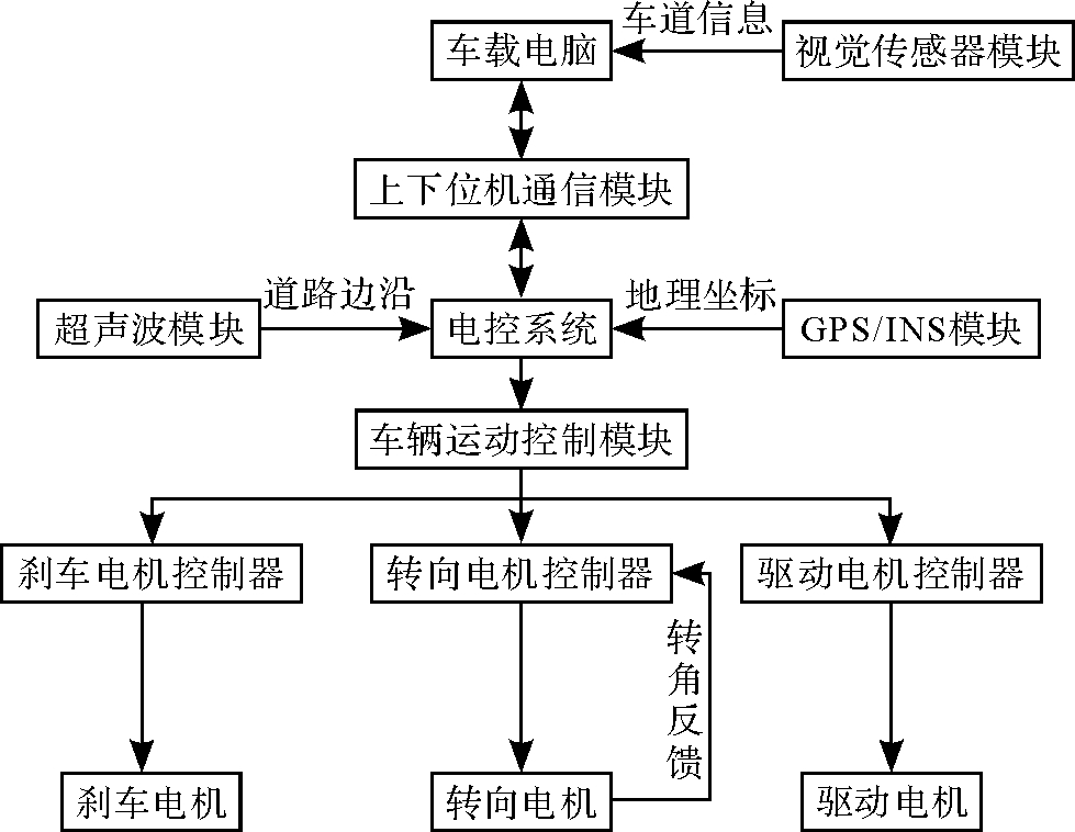
    多传感器融合的智能车定位导航系统为由车载电脑和电控系统共同构成的双核心架构,车载电脑为双核心架构的上位机,电控系统为双核心架构的下位机,通过上下位机通信模块实现双核间通信。整个系统按功能可细分为GPS/INS模块、视觉传感器模块、超声波模块和车辆运动控制模块这4个功能模块,其总体架构如图1所示。

    图1
                            多传感器融合的智能车定位导航系统总体架构

    图1 多传感器融合的智能车定位导航系统总体架构

    Fig. 1 Overall architecture of intelligent vehicle positioning and navigation system based on MSF

    在该定位导航系统中,车载电脑负责处理交换量大、计算能力要求高的数据,电控系统负责处理交换量小、实时性要求高的数据。首先,利用GPS/INS模块获取智能车地理坐标,依据地理坐标在OSM(open street map,公开地图)数据中检索与之匹配的空间数据,提取当前道路的车道数量和车道宽度;然后,利用视觉传感器模块检测前方车道线,利用超声波模块检测道路边沿;最后,对车道线和道路边沿数据进行深度融合,实现车道级智能车定位导航。

  • 2 多传感器融合的定位导航系统的硬件设计

    常见的硬件系统按硬件结构可划分为单板卡结构和双板卡结
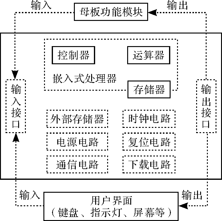
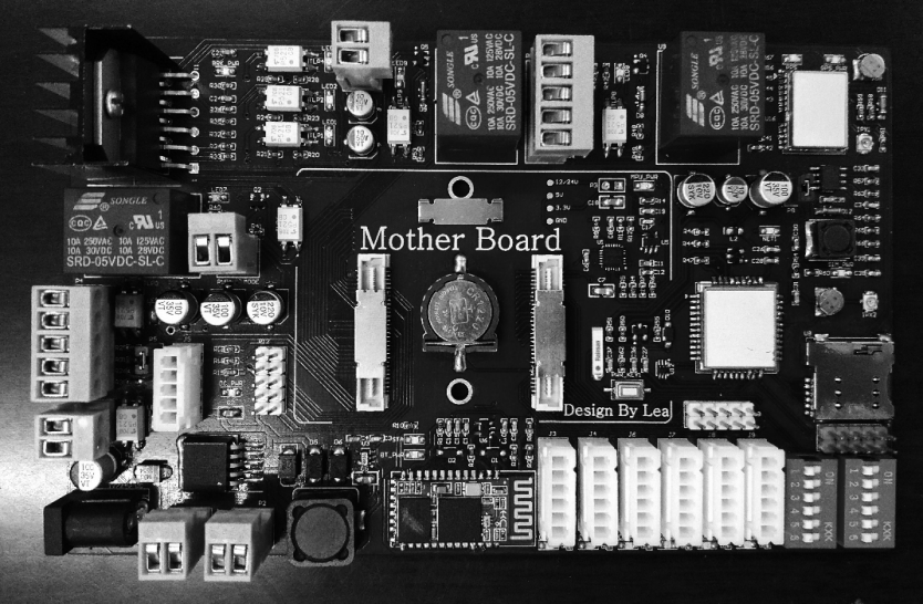
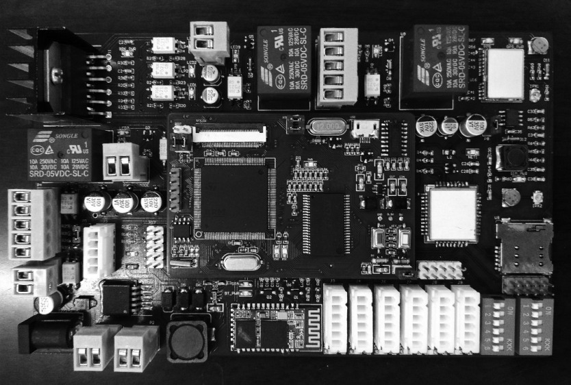
[6],本文所设计的多传感器融合的定位导航系统采用“核心板+母板”的双板卡结构,核心板与母板之间通过BTB(board to board,板对板)连接器实现连接。在双板卡结构中,核心板与母板均为双层PCB (printed circuit board,印刷电路板)线路板,该结构一方面具有4层PCB线路板体积小、质量轻和装配密度高等优势,另一方面能够显著降低开发成本,增强系统的通用性、可维护性和可扩展性。核心板是一块双层双面PCB线路板,它包括嵌入式处理器、外部存储器、时钟电路、电源电路、复位电路、通信电路、下载电路和输入/输出接口,如图2所示。

    图2
                            核心板硬件结构示意图

    图2 核心板硬件结构示意图

    Fig. 2 Hardware structure diagram of core board

    核心板的嵌入式处理器选用具有Cortex-M4内核的STM32F407ZGT6主控芯片,其工作主频高达168 MHz,芯片内集成1 024 kb Flash和192 kb SRAM(static random-access memory,静态随机存取存储器),内置硬件FPU(float point unit,浮点运算单元),支持DSP(digital signal processing, 数字信号处理)指令集。核心板的外部存储器选用IS62WV51216存储芯片,其容量为1 Mb,挂载于FSMC(flexible static memory controller, 可变静态存储控制器)上,作主控芯片扩展内存。核心板实物图如图3所示。

    图3
                            核心板实物图

    图3 核心板实物图

    Fig. 3 Physical drawing of core board

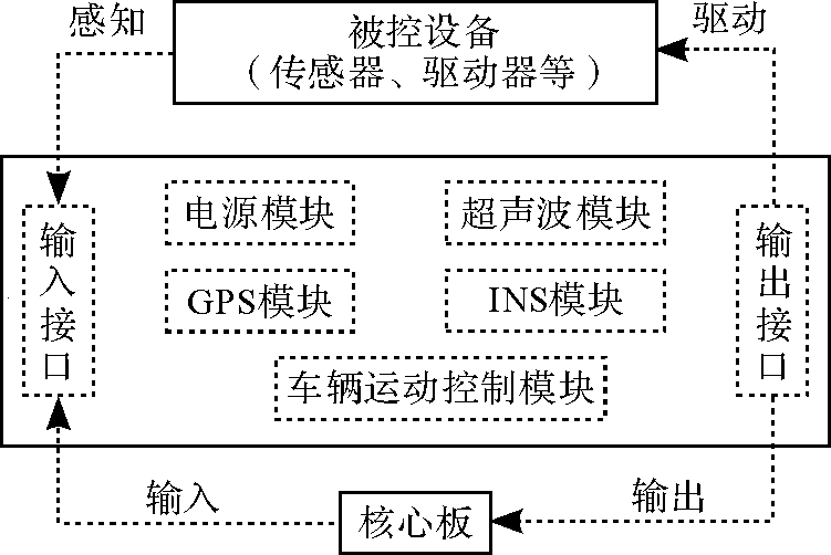
    母板是一块双层单面PCB线路板,它包括电源模块、超声波模块、GPS模块、INS模块、车辆运动控制模块和输入/输出接口,如图4所示。

    图4
                            母板硬件结构示意图

    图4 母板硬件结构示意图

    Fig. 4 Hardware structure diagram of mother board

    母板的GPS模块选用ZBT TG621S-BD芯片,INS模块选用MPU6050芯片,其中,ZBT TG621S-BD是一款167通道、三模全球定位导航接收器,其定位精度为2.5 m,最高更新频率为1 Hz;MPU6050是一款高性能六轴运动处理传感器,其上集成三轴MEMS(micro-electro mechanical system,微机电系统)加速度计、三轴陀螺仪和数字运动处理器。母板的超声波模块探头选用URM37传感器,URM37传感器自带微控制器,可极大地释放主控制器的软、硬件资源,4组URM37传感器分别平行布置于智能车左、右两侧。母板的车辆运动控制模块集成了驱动、转向和刹车电机控制系统,可依照电控系统控制指令控制智能车执行相应动作。母板实物图如图5所示,核心板与母板装配实物图如图6所示。

    图5
                            母板实物图

    图5 母板实物图

    Fig. 5 Physical drawing of mother board

    图6
                            核心板与母板装配实物图

    图6 核心板与母板装配实物图

    Fig. 6 Assembly physical drawing of core board and mother board

  • 3 多传感器融合的定位导航系统的软件设计

  • 3.1 基于机器视觉的车道线检测

    机器视觉车道线检测算法可分为基于模[7,8,9]、基于特[10]和基于区[11]的车道线检测算法,其中,基于模板的车道线检测算法抗噪性强、效果稳定、应用广,因此本文设计的系统采用基于模板的机器视觉车道线检测算法,该系统的视觉传感器主要性能参数如表1所示。

    表1 视觉传感器主要性能参数

    Table 1 Key performance parameters of vision sensor

    参数类型性能指标量值
    相机参数目数单目
    帧率10帧/s
    分辨率640×480 像素
    安装参数俯仰角0°~ 45°
    偏航角
    安装高度1.5 m

    所设计系统采用的基于模板的机器视觉车道线检测算法工作原理:1)相机标定,利用OpenCV标定库函数进行相机内、外参数标[12],确定三维空间与二维图像的对应关系;2)逆透视变换,利用IPM(inverse perspective transform, 逆透视变换)算法求解逆透视变换矩阵H和反逆透视变换矩阵Hinv[13],建立世界坐标系与图像坐标系的映射关系,获取IPM图像;3)图像预处理,对IPM图像进行阈值化处理,剔除左、右边界,利用高斯滤波器对IPM图像进行平滑处理,利用形态学腐蚀消除“斑点”噪声,对降噪后图像再作阈值化处理,获取预处理图像;4)边缘检测,利用Canny算子将预处理图像各独立边拼接为轮廓;5)直线检测,利用PPHT(progressive probabilistic Hough transform,累计概率霍夫变换)进行累加,提取边缘轮廓中的直线特征;6)曲线拟合,过滤、合并各直线掩码区,利用RANSAC(random sample consensus, 随机抽样一致)算法依次在每个掩码区内选取局内[14],并进行贝塞尔曲线拟[15],之后对每个掩码区的拟合曲线进行评分,保留得分最高的样条曲线;7)图像后处理,在IPM图像上扩展保留的样条曲线,再次进行贝塞尔曲线拟合,对拟合后的样条曲线特征点进行反逆透视变换,并将变换后样条曲线融合到原始图像上,最后对转换后曲线进行匹配,剔除变换过程中产生的噪声,获取后处理图像。基于模板的机器视觉车道线检测算法流程如图7所示。

    图7
                            基于模板的机器视觉车道线检测算法流程

    图7 基于模板的机器视觉车道线检测算法流程

    Fig. 7 Flow of lane line detection algorithm based on template-based machine vision

    基于模板的车道线检测算法中部分关键参数如下:图像预处理部分高斯滤波器采用非对称高斯核,垂直方向上Sigma(即标准差)值取5,水平方向Sigma值取7;直线检测部分利用PPHT的累加阈值取75;图像后处理部分曲线扩展角度阈值系数取0.7。基于模板的机器视觉车道线检测结果如图8所示。

    图8
                            基于模板的机器视觉车道线检测结果

    图8 基于模板的机器视觉车道线检测结果

    Fig. 8 Result of lane line detection based on template-based machine vision

    针对简单、结构化道路环境,本文设计的定位导航系统的车道线检测算法能够有效提取输入图像中的车道线特征,但存在部分特征误检问题,如图8(f)后处理图像中左侧道路边沿存在误检。在简单、结构化道路系统中,车道内部环境相对简单,环境干扰因素大多来自于车道外部。若能够获取道路边沿数据,并与车道线检测数据融合,可有效滤除环境干扰因素引起的误检。

  • 3.2 基于超声波雷达的道路边沿检测

    按照相关规定,三级以上多车道公路每条车道宽度多为330~375 cm,小型轿车宽度多为150~200 cm。车辆定位导航系统对车辆横向定位精度的要求要远高于纵向定位精度,且纵向定位误差可通过扩大跟车距离予以补偿,而横向定位误差则难以补
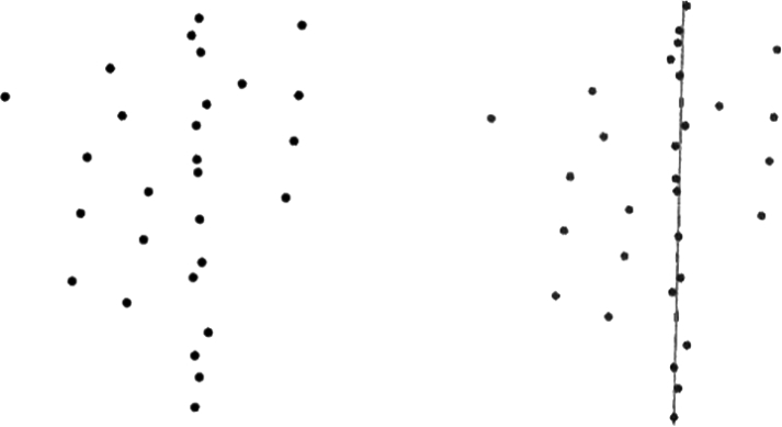
[16,17,18]。因此本文的定位导航系统设置4组超声波传感器,获取道路边沿数据,以提高横向定位精度。同时,通过道路边沿数据与车道线检测数据融合来滤除车道外环境干扰。4组超声波传感器平行布置于智能车左、右两侧,如图9所示。

    图9
                            超声波传感器位置示意图

    图9 超声波传感器位置示意图

    Fig. 9 Location diagram of ultrasonic sensor

    超声波传感器采集的数据为传感器安装位置到道路边沿的距离,将采集的距离数据投影至道路平面可得左、右两组点集,两组点集均由“局内点”和“局外点”构成,“局内点”为适应当前道路边沿模型的距离数据,“局外点”为不能适应当前道路模型的距离数据。在本模型中,产生“局外点”的因素主要包括超声波传感器误检和行人、车辆等引起的环境噪声两类。“局外点”为道路边沿检测的噪声,须通过RANSAC算法滤除,具体工作流程:1)从数据点集中随机抽取2组数据作为样本点;2)依据样本点计算模型参数,建立估计模型;3)用估计模型遍历所有数据点,计算错误率,标记“局内点”;4)通过标记的“局内点”重新估计模型;5)以重新估计的模型遍历所有数据点,计算错误率,标记“局内点”;6)通过重新标记的“局内点”与模型的错误率评估模型。重复执行上述步骤,循环迭代至退出条件,结果如图10所示。

    图10
                            基于RANSAC算法的道路边沿检测图

    图10 基于RANSAC算法的道路边沿检测图

    Fig. 10 Diagram of road edge detection based on RANSAC algorithm

    通过RANSAC算法提取道路边沿特征后,利用阈值化方法解析道路边沿数据,即可确定当前车道与道路边沿的相对位置关系。设当前车道ii∈{1,2,3,4})中心与道路左边沿距离为DLii=1,2,3,4),当前车道中心与道路右边沿距离为DRii=1,2,3,4),当前车道与道路边沿距离关系如图11所示。

    图11
                            当前车道与道路边沿距离关系

    图11 当前车道与道路边沿距离关系

    Fig. 11 Distance relationship of current lane and road edge

    图中d1d2d3d4依次为机动车道1,2,3和非机动车道4的宽度。结合图中距离关系,分别解析智能车单侧前、后超声波传感器采集的道路边沿距离差值,即可识别智能车是否存在变道倾向;结合图11中左、右道路边沿对应关系,解析道路边沿距离数据,即可确定智能车当前车道信息。

  • 3.3 多传感器数据融合

    本文设计的定位导航系统的多传感器数据融合是指GPS/INS定位数据、OSM数据、车道线检测数据和道路边沿检测数据的融合,主要包含2个方面:一是GPS/INS数据与OSM数据匹配,二是车道线检测数据与道路边沿检测数据匹配。

    OSM数据可分为空间数据和属性数据两类,其中,空间数据主要由点(nodes)、路(ways)和关系(relation) 3种元素构[19]。GPS/INS数据与OSM数据匹配的工作原理为:首先,通过GPS/INS模块获取经、纬度和高程坐标数据;然后,在OSM数据中检索与定位数据匹配的空间数据,提取当前道路的车道数量和车道宽度。

    本文设计的定位导航系统中车道线检测数据以像素坐标系Op-UV为测量基准,道路边沿检测数据以世界坐标系Ow-XwYwZw为测量基准,像素坐标系OP-UV与世界坐标系Ow-XwYwZw可通过相机坐标系Oc-XcYcZc建立转换关系,如图12所示。

    图12
                            不同坐标系间的转换关系

    图12 不同坐标系间的转换关系

    Fig. 12 Conversion relationship between different coordinate systems

    在世界坐标系下,视觉传感器所检测到的某点P的坐标为 (xw, yw, zw),该点在对应的相机坐标系中的坐标为 (xc, yc, zc),在对应的像素坐标系中的坐标为 (up, vp)。P点由世界坐标系到像素坐标系的坐标变换过程如下:

    第1步,P点由世界坐标系到相机坐标系的坐标变换如式(1)所示。

    xcyczc1=Rt01xwywzw1
    (1)

    式中:t为3×1的平移矢量,是世界坐标系原点Ow在相机坐标系中的坐标;R为3×3的旋转矩阵,是相机光轴绕世界坐标系XwYwZw轴旋转角度φθψ的方向余弦总乘[20]

    本文定位导航系统的相机安装于智能车顶部中央,世界坐标系原点Ow位于相机正下方道路平面上,相机坐标系原点Oc位于相机质心,因此,t=01.0611.061Tφ=135°,θ=0°,ψ=0°。

    Rφ=1000cosφsinφ0-sinφcosφ=1000-22220-22-22
    Rθ=cosθ0-sinθ010sinθ0cosθ=100010001
    Rψ=cosψsinψ0-sinψcosψ0001=100010001
    R=RφRθRψ=1000-22220-22-22

    第2步,P点由相机坐标系到像素坐标系的坐标变换,如式(2)所示。

    zcupvp1=α0uo00βvo00010xcyczc1
    (2)

    式中:αβuovo为相机内参数;α为相机宽度方向焦距参数,β为相机高度方向焦距参数;uo,vo为像素坐标系的主光轴点的坐标,多为图像中心,表示相机光轴在像素坐标系中的偏移量,以像素为单位。

    相机所拍摄的图像遵循透视规律,即被测物体的宽度和高度随相机与物体间距离变化而变化。相机内参数可在相机标定时计算得出,本文所选相机标定后获取的相机内参数如下:α=785.732像素,β=785.687像素,uo,vo =(315.367,272.297)像素。

    在进行车道线检测数据与道路边沿检测数据匹配时,先对道路边沿检测数据进行坐标变换,将道路边沿检测数据投影为世界坐标系中道路平面上的点,然后将车道线检测IPM图像中特征点数据由像素坐标系映射到世界坐标系,之后融合道路边沿数据和车道线数据,滤除车道外部环境干扰因素,提高车道线检测准确性。

  • 4 定位导航实验与结果分析

  • 4.1 定位导航系统实验平台设计

    多传感器融合的智能车定位导航系统实验平台分为FZ-01实验台和JD-3智能车两部分。具体工作流程如下:先按照系统实际性能需求搭建FZ-01实验台,并在实验台上进行模拟实验,完成定位导航系统软、硬件联合调试;待软、硬件联调完成后,将软、硬件系统移到JD-3智能车上,进行实车调试。多传感器融合的智能车定位导航系统实验平台如图13所示。

    图13
                            多传感器融合的智能车定位导航系统实验平台

    图13 多传感器融合的智能车定位导航系统实验平台

    Fig. 13 Experimental platform of intelligent vehicle positioning and navigation system based on MSF

  • 4.2 定位导航实验结果分析

    多传感器融合的智能车定位导航系统软、硬件测试实验过程如下:首先,依据GPS/INS模块获取的智能车当前经、纬度和高程坐标在OSM数据中检索匹配的道路信息,并提取当前道路的车道数量和车道宽度;然后,将提取的道路信息作为道路边沿检测部分的输入项,识别智能车当前所处车道信息;最后,将道路边沿检测数据与车道线检测数据融合,实现车辆定位导航。

    在车道线与道路边沿检测数据匹配时,以世界坐标系为基准,将道路边沿检测数据投影至世界坐标系。在对原始图像进行逆透视变换时,所选取地面特征点均以Ow为原点,测量它们在世界坐标系下的坐标,最后以道路边沿点数据作直线,用阈值化方法建立滤波边界,并将边界外侧像素清零,滤除车道外部环境干扰。滤波前后车道线检测结果对比如图14所示。

    图14
                            滤波前后车道线检测结果

    图14 滤波前后车道线检测结果

    Fig. 14 Detection result of lane line before and after filtering

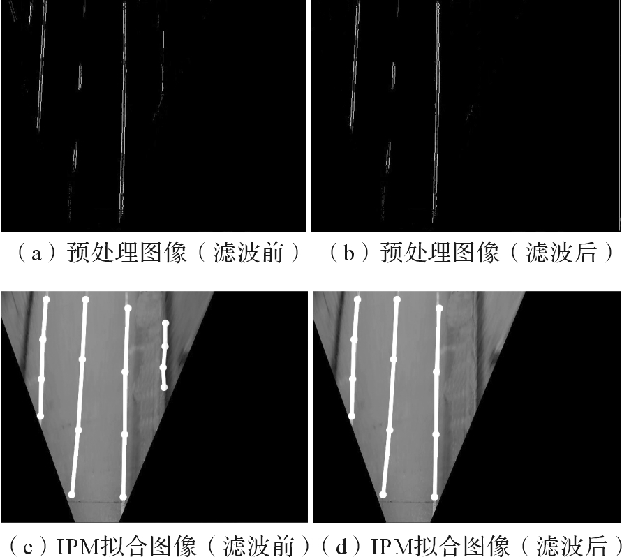
    分析图14车道线检测结果可知,图14(a)滤波前预处理图像左上角和右上角存在部分车道受外部环境干扰,其中:左上角部分范围小、线性弱,可通过车道线检测算法滤除,不会对车道线检测产生干扰;右上角部分范围大、线性强,无法通过车道线检测算法滤除,会引起车道线误检,如图14(c)所示。在引入道路边沿检测数据,并结合车道宽度数据设置阈值作滤波边界后,显著减少了车道外部环境干扰,图14(a)和图14(c)中左上角和右上角大部分干扰像素被滤除,仅残留部分滤波边界内的散点干扰像素,不会对车道线检测产生影响,如图14(b)和14(d)所示。实验结果表明车道线检测数据与道路边沿检测数据融合后,能够有效减少车道外部环境干扰,可提高车道线检测准确性。

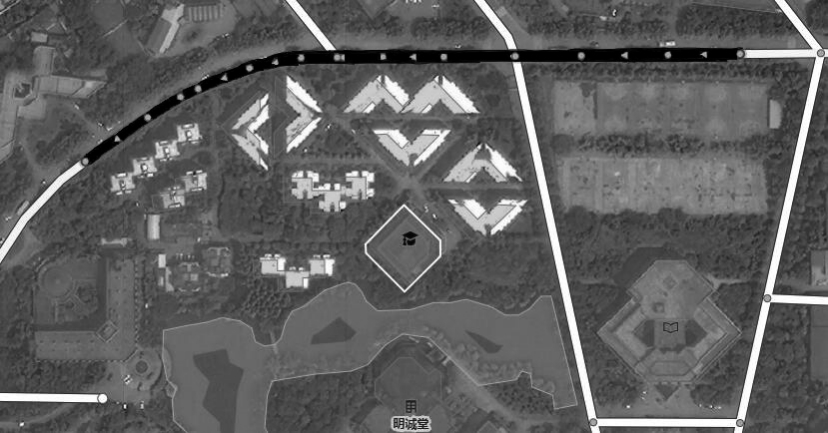
    软、硬件联调结束后,开始选取测试路径,准备进行道路测试。本文所设计的智能车定位导航系统主要针对简单、结构化道路环境,因此选取一段校园道路进行测试,如图15所示,图中黑色轨迹线为所选取的测试路径。

    图15
                            定位导航实验测试路径

    图15 定位导航实验测试路径

    Fig. 15 Diagram of test path for positioning and navigation experiment

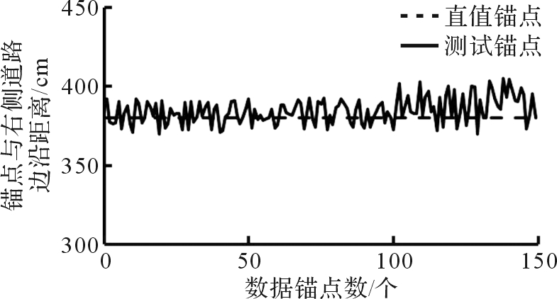
    本文所采集的数据集取自一段简单、结构化道路,数据的真值和测试值均通过定距人工标注法获得。在测试开始前,采用人工标注方式在测试路径上等间距处设置真值锚点;之后进行道路测试,采用人工标注的方式在测试路径上等间距处采集测试锚点数据;最后将所采集的测试锚点数据与真值锚点数据进行对比分析,对智能车定位导航系统性能指标进行验证。

    本次测试在一段双向单车道上进行,共设置150个测试锚点。测试道路的非机动车道宽度为230 cm,机动车道宽度为300 cm,具备完整的道路边沿特征。测试结果如图16所示。其中,真值锚点数据数据为当前行驶车道中心到右侧道路边沿的距离。

    图16
                            多传感器融合的智能车定位导航系统测试结果

    图16 多传感器融合的智能车定位导航系统测试结果

    Fig. 16 Test result of intelligent vehicle positioning and navigation system based on MSF

    分析图16的测试结果易得:1)测试锚点数据与真值锚点数据的差值在-30~30 cm的阈值范围内随机波动,表明多传感器融合的定位导航系统的性能相对稳定,优于传统GPS/INS组合定位导航系统的米级精度;2)测试曲线后半部分波动幅度明显高于前半部分波动幅度,且大部分测试锚点数据的值大于真值锚点数据的值,表明进入弯道后智能车行驶轨迹更靠近车道分界线,且在进行入弯方向修正时存在迟滞现象,导致数据波动幅度明显变大。测试结果表明智能车实际运行过程相对平稳,可基本实现简单、结构化道路环境下自动驾驶。

  • 5 结束语

    针对传统定位导航系统存在的精度低、成本高、鲁棒性差等问题,从实际需求出发,设计了一种多传感器融合的智能车定位导航系统。首先进行多传感器融合的智能车定位导航系统的总体架构设计,然后进行导航系统的硬件和软件设计,最后对系统进行实验分析,分析结果验证了多传感器融合的智能车定位导航系统设计的合理性,满足设计要求。

  • 参考文献

    • 1

      FAOUZI N E E, LEUNG H, KURIAN A. Data fusion in intelligent transportation systems: progress and challenge-A survey[J]. Information Fusion, 2010, 12(1): 4-10. doi:10.1016/j.inffus.2010.06.001

    • 2

      曾庆喜,冯玉朋,杜金枝,等.融合视觉的智能车组合导航技术分析[J].导航定位学报,2017,5(2):1-6. doi:10.3969/j.issn.2095-4999.2017.02.001

      ZENG Qing-xi, FENG Yu-peng, DU Jin-zhi, et al. Analysis on integrated navigation technology for intelligent vehicles by integrating vision[J]. Journal of Navigation and Positioning, 2017, 5(2): 1-6.

    • 3

      石慧.基于多传感器融合的车辆导航系统研究与实现[D].北京:北京工业大学城市交通学院,2016:7-10.

      SHI Hui. The research and implementation of vehicle navigation system based on multi-sensor fusion[D]. Beijing: Beijing University of Technology, College of Metropolitan Transportation, 2016: 7-10.

    • 4

      姜岩,赵熙俊,龚建伟,等.简单城市环境下地面无人驾驶系统的设计研究[J].机械工程学报,2012,48(20):106-115. doi:10.3901/JME.2012.20.103

      JIANG Yan, ZHAO Xi-jun, GONG Jian-wei, et al. System design of self-driving in simplified urban environments[J]. Journal of Mechanical Engineering, 2012, 48(20): 106-115.

    • 5

      HILLEL A B, LERNER R, DAN L, et al. Recent progress in road and lane detection: a survey[J]. Machine Vision & Applications, 2014, 25(3): 727-745. doi:10.1007/s00138-011-0404-2

    • 6

      郭俊杰.无人驾驶车GPS自主导航系统设计与实现[D].西安:长安大学汽车学院,2014:2-17.

      GUO Jun-jie. GPS navigation system design and implementation for driverless smart vehicles[D]. Xi’an: Chang’an University, School of Automobile, 2014: 2-17.

    • 7

      WANG Y, TEOH E K, SHEN D. Lane detection and tracking using B-Snake[J]. Image & Vision Computing, 2003, 22(4): 269-280. doi:10.1016/j.imavis.2003.10.003

    • 8

      叶美松.单目视觉的智能电动小车车道线识别与跟踪[D].成都:西南交通大学机械工程学院,2017:2-15.

      YE Mei-song. Lane recognition and tracking of intelligent electric vehicle based on monocular vision[D]. Chengdu: Southwest Jiaotong University, School of Mechanical Engineering, 2017: 2-15.

    • 9

      JUNG C R, KELBER C R. Lane following and lane departure using a linear-parabolic model[J]. Image & Vision Computing, 2005, 23(13): 1192-1202. doi :10.1016/j.imavis.2005.07.018

    • 10

      王海,蔡英凤,林国余,等.基于方向可变Haar特征和双曲线模型的车道线检测方法[J].交通运输工程学报,2014,14(5):119-126. doi:10.3969/j.issn.1671-1637.2014.05.015

      WANG Hai, CAI Ying-feng, LIN Guo-yu, et al. Lane line detection method based on orientation variance Haar feature and hyperbolic model[J]. Journal of Traffic and Transportation Engineering, 2014, 14(5): 119-126.

    • 11

      鲁曼,蔡自兴,李仪.道路区域分割的车道线检测方法[J].智能系统学报,2010,5(6):505-509. doi:10.3969/j.issn.1673-4785.2010.06.007

      LU Man, CAI Zi-xing, LI Yi. A lane detection method based on road segmentation[J]. CAAI Transactions on Intelligent Systems, 2010, 5(6): 505-509.

    • 12

      KAEHLER A, BRADSKI G. Learning OpenCV 3: computer vision in C++ with the OpenCV library[M]. Sebastopol: O’Reilly Media Inc, 2016: 29-113.

    • 13

      刘洪涛,蒋如意,胡文,等.基于路面垂直轮廓建模的一般路面逆透视变换[J].上海交通大学学报,2012,46(11):1770-1773.

      LIU Hong-tao, JIANG Ru-yi, HU Wen, et al. Inverse perspective mapping of general road based on vertical road profile modeling[J]. Journal of Shanghai Jiaotong University, 2012, 46(11): 1770-1773.

    • 14

      SUN Qian, ZHANG Ya, WANG Jian-guo, et al. An improved fast feature extraction based on RANSAC method of vision/SINS integrated navigation system in GNSS-denied environments[J]. Advances in Space Research, 2017, 60(12): 2660-2671. doi:10.1016/j.asr.2017.05.017

    • 15

      侯长征.基于视觉的车道线检测技术研究[D].成都:西南交通大学信息科学与技术学院,2017:29-35.

      HOU Chang-zheng. Research on vision-based lane markings detection technology[D]. Chengdu: Southwest Jiaotong University, School of Information Science and Technology, 2017: 29-35.

    • 16

      曹立波,陈峥,颜凌波,等.基于RFID、视觉和UWB的车辆定位系统[J].汽车工程,2017,39(2):225-231. doi:CNKI:SUN:QCGC.0.2017-02-017

      CAO Li-bo, CHEN Zheng, YAN Ling-bo, et al. Vehicle positioning system based on RFID, Vision and UWB[J]. Automotive Engineering, 2017, 39(2): 225-231.

    • 17

      段建民,石慧,刘丹,等.无人驾驶智能车导航系统控制研究[J].计算机仿真,2016,33(2):198-203. doi:10.3969/j.issn.1006-9348.2016.02.042

      DUAN Jian-min, SHI Hui, LIU Dan, et al. Research of navigation control system for unmanned intelligent vehicles[J]. Computer Simulation, 2016, 33(2): 198-203.

    • 18

      赵翔,杨明,王春香,等.基于视觉和毫米波雷达的车道级定位方法[J].上海交通大学学报,2018,52(1):33-38. doi:10.16183/j.cnki.jsjtu.2018.01.006

      ZHAO Xiang, YANG Ming, WANG Chun-xiang, et al. A lane-level positioning method based on vision and millimeter wave radar[J]. Journal of Shanghai Jiaotong University, 2018, 52(1): 33-38.

    • 19

      李龙.基于OSM的移动GIS系统的研究与实现[D].北京:北京邮电大学自动化学院,2016:6-8.

      LI Long. Research and implementation of the mobile GIS system based on OSM[D]. Beijing: Beijing University of Posts and Telecommunications, School of Automation, 2016: 6-8.

    • 20

      王晨学,平雪良,徐超.基于视觉辅助定位的机械臂运动学参数辨识研究[J].工程设计学报,2018,25(1):27-34. doi:10.3785/j.issn.1006-754X.2018.01.004

      WANG Chen-xue, PING Xue-liang, XU Chao. Research on the kinematic parameter identification of robot arm based on the assistant location by stereo vision[J]. Chinese Journal of Engineering Design, 2018, 25(1): 27-34.

李磊

机 构:西南交通大学 机械工程学院, 四川 成都 610031

Affiliation:School of Mechanical Engineering, Southwest Jiaotong University, Chengdu 610031, China

邮 箱:swjtu_lilei@163.com

作者简介:李磊(1994—),男,云南昆明人,硕士生,从事机器视觉与运动控制研究,E-mail:swjtu_lilei@163.com

肖世德

机 构:西南交通大学 机械工程学院, 四川 成都 610031

Affiliation:School of Mechanical Engineering, Southwest Jiaotong University, Chengdu 610031, China

角 色:通讯作者

Role:Corresponding author

邮 箱:sdxiao@swjtu.edu.cn

作者简介:肖世德(1967—),男,四川仁寿人,教授,博士生导师,博士,从事机械系统CAD /CAM和PDM/CIMS、智能化网络化机电工业监测和控制系统等研究,E-mail:sdxiao@swjtu.edu.cn,https://orcid.org/0000-0001-9876-1016

李兴坤

机 构:西南交通大学 机械工程学院, 四川 成都 610031

Affiliation:School of Mechanical Engineering, Southwest Jiaotong University, Chengdu 610031, China

董庆丰

机 构:西南交通大学 机械工程学院, 四川 成都 610031

Affiliation:School of Mechanical Engineering, Southwest Jiaotong University, Chengdu 610031, China

1006-754X-2019-26-2-182/alternativeImage/c5a58cdd-2423-4085-8337-ec25f024270c-F001.jpg
1006-754X-2019-26-2-182/alternativeImage/c5a58cdd-2423-4085-8337-ec25f024270c-F002.jpg
1006-754X-2019-26-2-182/alternativeImage/c5a58cdd-2423-4085-8337-ec25f024270c-F003.jpg
1006-754X-2019-26-2-182/alternativeImage/c5a58cdd-2423-4085-8337-ec25f024270c-F004.jpg
1006-754X-2019-26-2-182/alternativeImage/c5a58cdd-2423-4085-8337-ec25f024270c-F005.jpg
1006-754X-2019-26-2-182/alternativeImage/c5a58cdd-2423-4085-8337-ec25f024270c-F006.jpg
参数类型性能指标量值
相机参数目数单目
帧率10帧/s
分辨率640×480 像素
安装参数俯仰角0°~ 45°
偏航角
安装高度1.5 m
1006-754X-2019-26-2-182/alternativeImage/c5a58cdd-2423-4085-8337-ec25f024270c-F007.jpg
1006-754X-2019-26-2-182/alternativeImage/c5a58cdd-2423-4085-8337-ec25f024270c-F008.jpg
1006-754X-2019-26-2-182/alternativeImage/c5a58cdd-2423-4085-8337-ec25f024270c-F009.jpg
1006-754X-2019-26-2-182/alternativeImage/c5a58cdd-2423-4085-8337-ec25f024270c-F010.jpg
1006-754X-2019-26-2-182/alternativeImage/c5a58cdd-2423-4085-8337-ec25f024270c-F011.jpg
1006-754X-2019-26-2-182/alternativeImage/c5a58cdd-2423-4085-8337-ec25f024270c-F012.jpg
1006-754X-2019-26-2-182/alternativeImage/c5a58cdd-2423-4085-8337-ec25f024270c-F013.jpg
1006-754X-2019-26-2-182/alternativeImage/c5a58cdd-2423-4085-8337-ec25f024270c-F017.jpg
1006-754X-2019-26-2-182/alternativeImage/c5a58cdd-2423-4085-8337-ec25f024270c-F014.jpg
1006-754X-2019-26-2-182/alternativeImage/c5a58cdd-2423-4085-8337-ec25f024270c-F015.jpg

图1 多传感器融合的智能车定位导航系统总体架构

Fig. 1 Overall architecture of intelligent vehicle positioning and navigation system based on MSF

图2 核心板硬件结构示意图

Fig. 2 Hardware structure diagram of core board

图3 核心板实物图

Fig. 3 Physical drawing of core board

图4 母板硬件结构示意图

Fig. 4 Hardware structure diagram of mother board

图5 母板实物图

Fig. 5 Physical drawing of mother board

图6 核心板与母板装配实物图

Fig. 6 Assembly physical drawing of core board and mother board

表1 视觉传感器主要性能参数

Table 1 Key performance parameters of vision sensor

图7 基于模板的机器视觉车道线检测算法流程

Fig. 7 Flow of lane line detection algorithm based on template-based machine vision

图8 基于模板的机器视觉车道线检测结果

Fig. 8 Result of lane line detection based on template-based machine vision

图9 超声波传感器位置示意图

Fig. 9 Location diagram of ultrasonic sensor

图10 基于RANSAC算法的道路边沿检测图

Fig. 10 Diagram of road edge detection based on RANSAC algorithm

图11 当前车道与道路边沿距离关系

Fig. 11 Distance relationship of current lane and road edge

图12 不同坐标系间的转换关系

Fig. 12 Conversion relationship between different coordinate systems

图13 多传感器融合的智能车定位导航系统实验平台

Fig. 13 Experimental platform of intelligent vehicle positioning and navigation system based on MSF

图14 滤波前后车道线检测结果

Fig. 14 Detection result of lane line before and after filtering

图15 定位导航实验测试路径

Fig. 15 Diagram of test path for positioning and navigation experiment

图16 多传感器融合的智能车定位导航系统测试结果

Fig. 16 Test result of intelligent vehicle positioning and navigation system based on MSF

image /

无注解

无注解

无注解

无注解

无注解

无注解

无注解

无注解

无注解

无注解

无注解

无注解

无注解

无注解

无注解

无注解

无注解

无注解

  • 参考文献

    • 1

      FAOUZI N E E, LEUNG H, KURIAN A. Data fusion in intelligent transportation systems: progress and challenge-A survey[J]. Information Fusion, 2010, 12(1): 4-10. doi:10.1016/j.inffus.2010.06.001

    • 2

      曾庆喜,冯玉朋,杜金枝,等.融合视觉的智能车组合导航技术分析[J].导航定位学报,2017,5(2):1-6. doi:10.3969/j.issn.2095-4999.2017.02.001

      ZENG Qing-xi, FENG Yu-peng, DU Jin-zhi, et al. Analysis on integrated navigation technology for intelligent vehicles by integrating vision[J]. Journal of Navigation and Positioning, 2017, 5(2): 1-6.

    • 3

      石慧.基于多传感器融合的车辆导航系统研究与实现[D].北京:北京工业大学城市交通学院,2016:7-10.

      SHI Hui. The research and implementation of vehicle navigation system based on multi-sensor fusion[D]. Beijing: Beijing University of Technology, College of Metropolitan Transportation, 2016: 7-10.

    • 4

      姜岩,赵熙俊,龚建伟,等.简单城市环境下地面无人驾驶系统的设计研究[J].机械工程学报,2012,48(20):106-115. doi:10.3901/JME.2012.20.103

      JIANG Yan, ZHAO Xi-jun, GONG Jian-wei, et al. System design of self-driving in simplified urban environments[J]. Journal of Mechanical Engineering, 2012, 48(20): 106-115.

    • 5

      HILLEL A B, LERNER R, DAN L, et al. Recent progress in road and lane detection: a survey[J]. Machine Vision & Applications, 2014, 25(3): 727-745. doi:10.1007/s00138-011-0404-2

    • 6

      郭俊杰.无人驾驶车GPS自主导航系统设计与实现[D].西安:长安大学汽车学院,2014:2-17.

      GUO Jun-jie. GPS navigation system design and implementation for driverless smart vehicles[D]. Xi’an: Chang’an University, School of Automobile, 2014: 2-17.

    • 7

      WANG Y, TEOH E K, SHEN D. Lane detection and tracking using B-Snake[J]. Image & Vision Computing, 2003, 22(4): 269-280. doi:10.1016/j.imavis.2003.10.003

    • 8

      叶美松.单目视觉的智能电动小车车道线识别与跟踪[D].成都:西南交通大学机械工程学院,2017:2-15.

      YE Mei-song. Lane recognition and tracking of intelligent electric vehicle based on monocular vision[D]. Chengdu: Southwest Jiaotong University, School of Mechanical Engineering, 2017: 2-15.

    • 9

      JUNG C R, KELBER C R. Lane following and lane departure using a linear-parabolic model[J]. Image & Vision Computing, 2005, 23(13): 1192-1202. doi :10.1016/j.imavis.2005.07.018

    • 10

      王海,蔡英凤,林国余,等.基于方向可变Haar特征和双曲线模型的车道线检测方法[J].交通运输工程学报,2014,14(5):119-126. doi:10.3969/j.issn.1671-1637.2014.05.015

      WANG Hai, CAI Ying-feng, LIN Guo-yu, et al. Lane line detection method based on orientation variance Haar feature and hyperbolic model[J]. Journal of Traffic and Transportation Engineering, 2014, 14(5): 119-126.

    • 11

      鲁曼,蔡自兴,李仪.道路区域分割的车道线检测方法[J].智能系统学报,2010,5(6):505-509. doi:10.3969/j.issn.1673-4785.2010.06.007

      LU Man, CAI Zi-xing, LI Yi. A lane detection method based on road segmentation[J]. CAAI Transactions on Intelligent Systems, 2010, 5(6): 505-509.

    • 12

      KAEHLER A, BRADSKI G. Learning OpenCV 3: computer vision in C++ with the OpenCV library[M]. Sebastopol: O’Reilly Media Inc, 2016: 29-113.

    • 13

      刘洪涛,蒋如意,胡文,等.基于路面垂直轮廓建模的一般路面逆透视变换[J].上海交通大学学报,2012,46(11):1770-1773.

      LIU Hong-tao, JIANG Ru-yi, HU Wen, et al. Inverse perspective mapping of general road based on vertical road profile modeling[J]. Journal of Shanghai Jiaotong University, 2012, 46(11): 1770-1773.

    • 14

      SUN Qian, ZHANG Ya, WANG Jian-guo, et al. An improved fast feature extraction based on RANSAC method of vision/SINS integrated navigation system in GNSS-denied environments[J]. Advances in Space Research, 2017, 60(12): 2660-2671. doi:10.1016/j.asr.2017.05.017

    • 15

      侯长征.基于视觉的车道线检测技术研究[D].成都:西南交通大学信息科学与技术学院,2017:29-35.

      HOU Chang-zheng. Research on vision-based lane markings detection technology[D]. Chengdu: Southwest Jiaotong University, School of Information Science and Technology, 2017: 29-35.

    • 16

      曹立波,陈峥,颜凌波,等.基于RFID、视觉和UWB的车辆定位系统[J].汽车工程,2017,39(2):225-231. doi:CNKI:SUN:QCGC.0.2017-02-017

      CAO Li-bo, CHEN Zheng, YAN Ling-bo, et al. Vehicle positioning system based on RFID, Vision and UWB[J]. Automotive Engineering, 2017, 39(2): 225-231.

    • 17

      段建民,石慧,刘丹,等.无人驾驶智能车导航系统控制研究[J].计算机仿真,2016,33(2):198-203. doi:10.3969/j.issn.1006-9348.2016.02.042

      DUAN Jian-min, SHI Hui, LIU Dan, et al. Research of navigation control system for unmanned intelligent vehicles[J]. Computer Simulation, 2016, 33(2): 198-203.

    • 18

      赵翔,杨明,王春香,等.基于视觉和毫米波雷达的车道级定位方法[J].上海交通大学学报,2018,52(1):33-38. doi:10.16183/j.cnki.jsjtu.2018.01.006

      ZHAO Xiang, YANG Ming, WANG Chun-xiang, et al. A lane-level positioning method based on vision and millimeter wave radar[J]. Journal of Shanghai Jiaotong University, 2018, 52(1): 33-38.

    • 19

      李龙.基于OSM的移动GIS系统的研究与实现[D].北京:北京邮电大学自动化学院,2016:6-8.

      LI Long. Research and implementation of the mobile GIS system based on OSM[D]. Beijing: Beijing University of Posts and Telecommunications, School of Automation, 2016: 6-8.

    • 20

      王晨学,平雪良,徐超.基于视觉辅助定位的机械臂运动学参数辨识研究[J].工程设计学报,2018,25(1):27-34. doi:10.3785/j.issn.1006-754X.2018.01.004

      WANG Chen-xue, PING Xue-liang, XU Chao. Research on the kinematic parameter identification of robot arm based on the assistant location by stereo vision[J]. Chinese Journal of Engineering Design, 2018, 25(1): 27-34.